How to Use 4 Channel XL4015 DC-DC : Examples, Pinouts, and Specs
Introduction
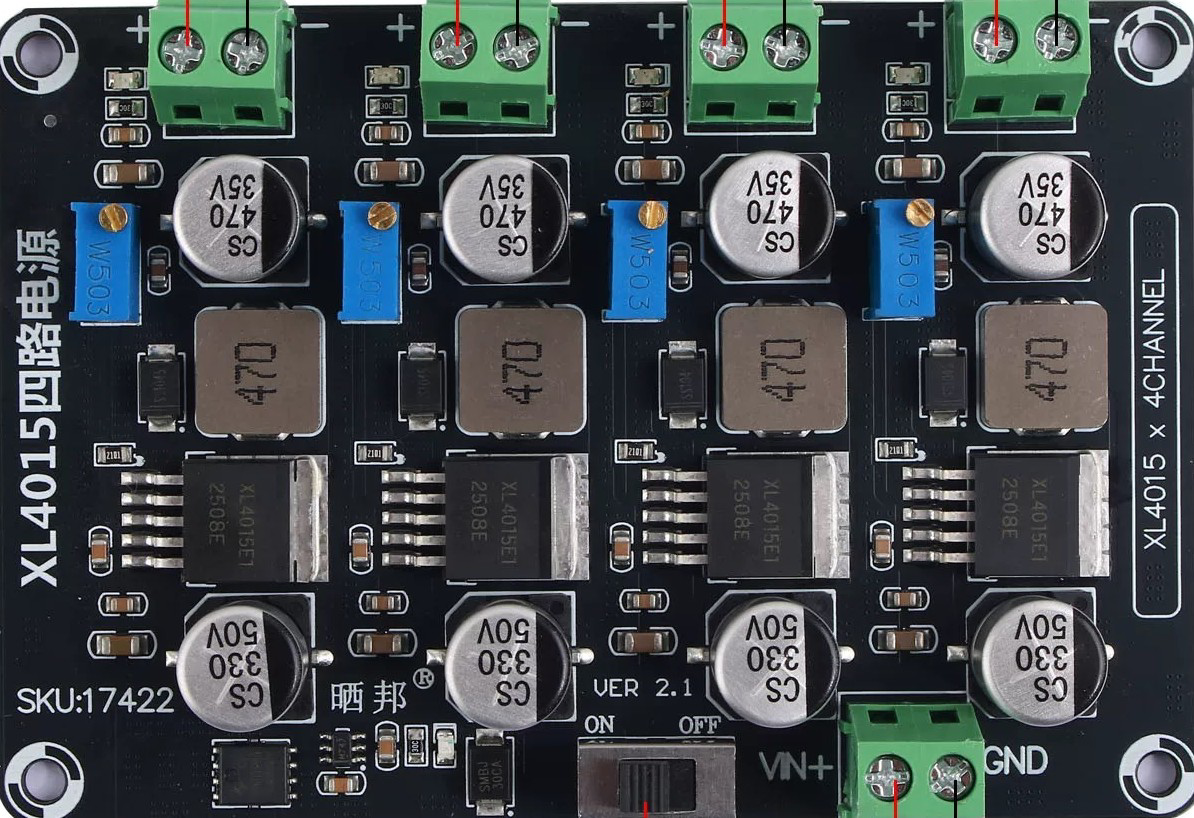
The 4 Channel XL4015 DC-DC is a versatile buck converter module designed to step down voltage efficiently. It features four independent channels, allowing users to power multiple devices or circuits simultaneously. With its high efficiency and adjustable output voltage, this module is ideal for applications requiring stable and reliable power delivery.
Explore Projects Built with 4 Channel XL4015 DC-DC


Explore Projects Built with 4 Channel XL4015 DC-DC
Common Applications
- Powering microcontrollers, sensors, and modules in embedded systems
- Battery charging applications
- LED drivers and lighting systems
- DIY electronics projects requiring multiple voltage outputs
- Power supply for robotics and automation systems
Technical Specifications
Below are the key technical details of the 4 Channel XL4015 DC-DC module:
General Specifications
| Parameter | Value |
|---|---|
| Input Voltage Range | 4V to 38V |
| Output Voltage Range | 1.25V to 36V (adjustable) |
| Maximum Output Current | 5A per channel (with proper cooling) |
| Efficiency | Up to 96% |
| Switching Frequency | 180 kHz |
| Operating Temperature | -40°C to +85°C |
| Dimensions | Varies by manufacturer (approx. 60mm x 40mm) |
Pin Configuration and Descriptions
Each channel of the XL4015 module has the following pin configuration:
| Pin Name | Description |
|---|---|
| VIN+ | Positive input voltage |
| VIN- | Negative input voltage (ground) |
| VOUT+ | Positive output voltage |
| VOUT- | Negative output voltage (ground) |
| ADJ | Potentiometer for adjusting output voltage |
Usage Instructions
How to Use the 4 Channel XL4015 DC-DC Module
Connect the Input Voltage:
- Connect the positive input voltage to the
VIN+pin and the ground to theVIN-pin. - Ensure the input voltage is within the specified range (4V to 38V).
- Connect the positive input voltage to the
Adjust the Output Voltage:
- Use the onboard potentiometer (
ADJ) to set the desired output voltage. - Turn the potentiometer clockwise to increase the output voltage and counterclockwise to decrease it.
- Use a multimeter to measure the output voltage for precise adjustment.
- Use the onboard potentiometer (
Connect the Load:
- Connect the positive terminal of your load to the
VOUT+pin and the ground to theVOUT-pin. - Ensure the load does not exceed the maximum current rating of 5A per channel.
- Connect the positive terminal of your load to the
Cooling Considerations:
- For high-current applications, attach a heatsink to the XL4015 IC to prevent overheating.
- Ensure proper ventilation around the module.
Power On:
- Once all connections are secure, power on the module and verify the output voltage and current.
Example: Using the XL4015 with an Arduino UNO
The XL4015 can be used to power an Arduino UNO by stepping down a higher voltage (e.g., 12V) to 5V. Below is an example setup:
- Connect a 12V power supply to the
VIN+andVIN-pins of one channel. - Adjust the output voltage to 5V using the potentiometer.
- Connect the
VOUT+pin to the Arduino's 5V pin and theVOUT-pin to the Arduino's GND pin.
Sample Arduino Code for Testing
The following code demonstrates how to blink an LED connected to the Arduino UNO powered by the XL4015 module:
// Simple LED Blink Example
// Ensure the XL4015 module is providing 5V to the Arduino UNO

const int ledPin = 13; // Built-in LED pin on Arduino UNO

void setup() {
  pinMode(ledPin, OUTPUT); // Set the LED pin as an output
}

void loop() {
  digitalWrite(ledPin, HIGH); // Turn the LED on
  delay(1000);               // Wait for 1 second
  digitalWrite(ledPin, LOW);  // Turn the LED off
  delay(1000);               // Wait for 1 second
}
Best Practices
- Always verify the input and output voltage levels before connecting sensitive devices.
- Use a fuse or current-limiting resistor for added protection in high-power applications.
- Avoid short circuits between the input and output terminals.
Troubleshooting and FAQs
Common Issues and Solutions
| Issue | Possible Cause | Solution |
|---|---|---|
| No output voltage | Incorrect wiring or loose connections | Double-check all connections and wiring. |
| Output voltage not adjustable | Faulty potentiometer or damaged module | Replace the potentiometer or module. |
| Overheating during operation | High current draw or poor ventilation | Add a heatsink and ensure proper airflow. |
| Output voltage fluctuates | Insufficient input voltage or load issue | Verify input voltage and check the load. |
FAQs
Can I use the XL4015 to charge batteries?
- Yes, but ensure the output voltage and current are set according to the battery's specifications.
What happens if I exceed the maximum current rating?
- Exceeding 5A per channel can damage the module. Use proper cooling and avoid overloading.
Can I use all four channels simultaneously?
- Yes, each channel operates independently. Ensure the input power supply can handle the combined load.
Is the XL4015 module reverse-polarity protected?
- No, connecting the input voltage in reverse can damage the module. Use a diode for protection.
By following this documentation, you can effectively use the 4 Channel XL4015 DC-DC module in your projects while ensuring safe and reliable operation.