How to Use senseBox: Examples, Pinouts, and Specs
Introduction
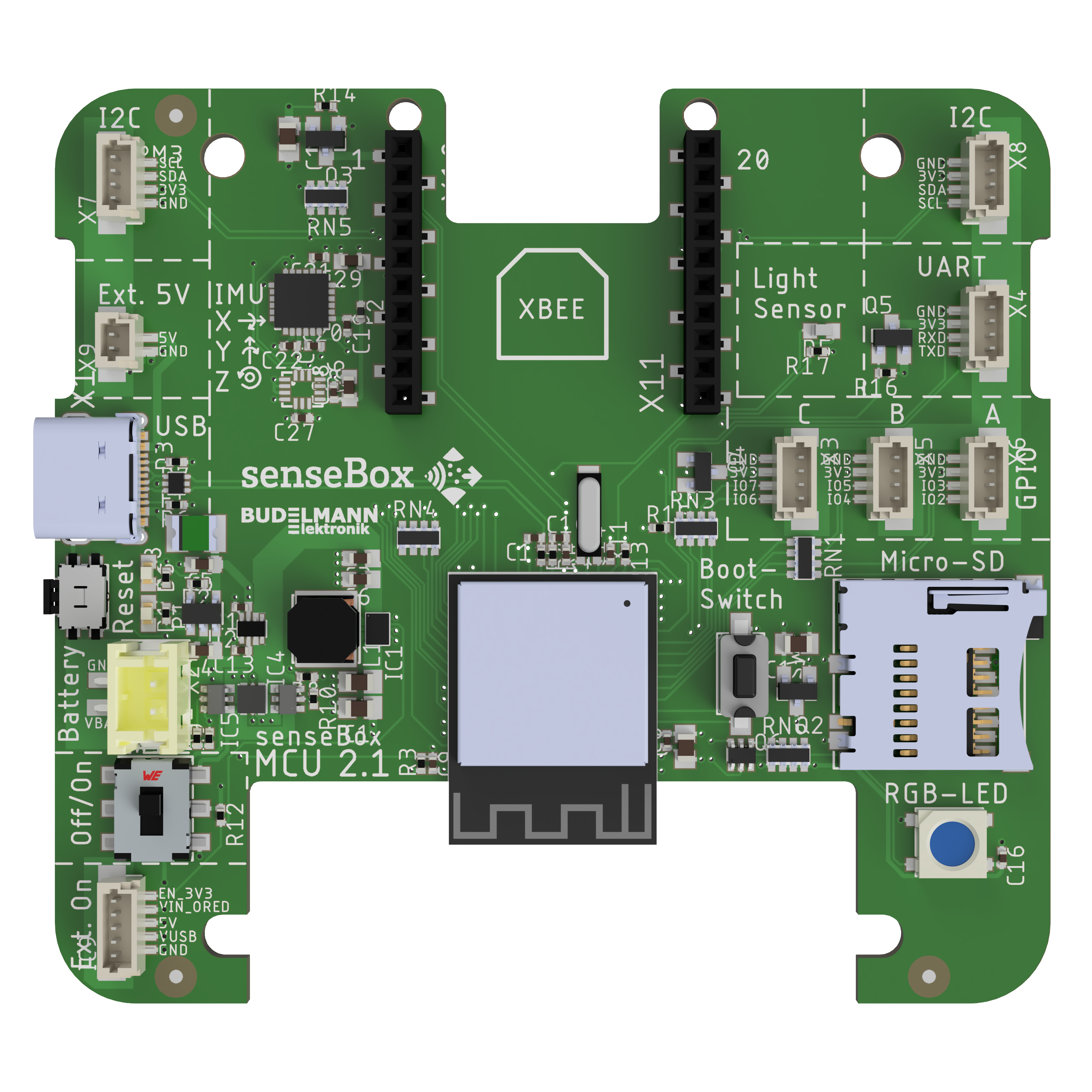
The senseBox is a modular IoT platform developed by Reedu with the part ID MCU S2. It is designed to simplify the process of creating and experimenting with sensor-based projects, making it an ideal tool for educational purposes. The senseBox allows users to connect various sensors and actuators to collect, process, and transmit data, enabling hands-on learning in fields such as environmental monitoring, smart cities, and IoT development.
Explore Projects Built with senseBox

Explore Projects Built with senseBox
Common Applications and Use Cases
- Environmental data collection (e.g., temperature, humidity, air quality)
- Smart city projects (e.g., traffic monitoring, noise pollution analysis)
- IoT prototyping and experimentation
- STEM education and workshops
- Weather station development
Technical Specifications
The senseBox is built to be user-friendly and versatile, with the following key technical details:
General Specifications
| Parameter | Value |
|---|---|
| Manufacturer | Reedu |
| Part ID | MCU S2 |
| Microcontroller | ESP32-based |
| Operating Voltage | 3.3V |
| Input Voltage (via USB) | 5V |
| Digital I/O Pins | 16 |
| Analog Input Pins | 6 |
| Communication Protocols | I2C, SPI, UART, Wi-Fi, BLE |
| Flash Memory | 4MB |
| Clock Speed | 240 MHz |
| Power Consumption | ~200 mA (active), ~10 mA (idle) |
Pin Configuration and Descriptions
The senseBox features a modular design with labeled connectors for easy sensor integration. Below is the pin configuration:
Pinout Table
| Pin Name | Type | Description |
|---|---|---|
| GND | Power | Ground connection |
| 3.3V | Power | 3.3V power output for sensors and modules |
| 5V | Power | 5V power output for sensors and modules |
| D0-D15 | Digital I/O | General-purpose digital input/output pins |
| A0-A5 | Analog Input | Analog input pins for sensors |
| SDA | I2C | I2C data line |
| SCL | I2C | I2C clock line |
| TX | UART | UART transmit pin |
| RX | UART | UART receive pin |
| SPI_MOSI | SPI | SPI Master Out Slave In |
| SPI_MISO | SPI | SPI Master In Slave Out |
| SPI_SCK | SPI | SPI clock line |
| SPI_SS | SPI | SPI slave select |
| EN | Power | Enable pin to activate the microcontroller |
| RST | Reset | Reset pin to restart the microcontroller |
Usage Instructions
The senseBox is designed to be beginner-friendly while offering advanced features for experienced users. Follow these steps to use the senseBox in a circuit:
Step 1: Powering the senseBox
- Connect the senseBox to a computer or USB power source using a micro-USB cable.
- Ensure the power source provides a stable 5V output.
Step 2: Connecting Sensors and Modules
- Use the labeled connectors to attach sensors and modules. For example:
- Connect I2C sensors to the SDA and SCL pins.
- Attach analog sensors to the A0-A5 pins.
- Use digital sensors or actuators with the D0-D15 pins.
Step 3: Programming the senseBox
- The senseBox is compatible with the Arduino IDE. Install the necessary board support package for ESP32-based devices.
- Write or upload your code to the senseBox using the Arduino IDE.
Example Code: Reading Temperature and Humidity
Below is an example of how to use the senseBox with a DHT11 temperature and humidity sensor:
#include <DHT.h>

// Define the pin where the DHT sensor is connected
#define DHTPIN D4  // Connect the DHT sensor to digital pin D4

// Define the type of DHT sensor (DHT11 or DHT22)
#define DHTTYPE DHT11

// Initialize the DHT sensor
DHT dht(DHTPIN, DHTTYPE);

void setup() {
  Serial.begin(9600);  // Start serial communication at 9600 baud
  dht.begin();         // Initialize the DHT sensor
  Serial.println("senseBox: Reading temperature and humidity...");
}

void loop() {
  // Read temperature and humidity values
  float humidity = dht.readHumidity();
  float temperature = dht.readTemperature();

  // Check if the readings are valid
  if (isnan(humidity) || isnan(temperature)) {
    Serial.println("Failed to read from DHT sensor!");
    return;
  }

  // Print the readings to the Serial Monitor
  Serial.print("Humidity: ");
  Serial.print(humidity);
  Serial.print("%  Temperature: ");
  Serial.print(temperature);
  Serial.println("°C");

  delay(2000);  // Wait 2 seconds before the next reading
}
Step 4: Uploading the Code
- Connect the senseBox to your computer via USB.
- Select the correct board and port in the Arduino IDE.
- Click the "Upload" button to transfer the code to the senseBox.
Important Considerations and Best Practices
- Always double-check the pin connections to avoid damage to the senseBox or sensors.
- Use appropriate pull-up resistors for I2C communication if required.
- Avoid exceeding the maximum current rating of the power pins.
- Use a stable power source to ensure reliable operation.
Troubleshooting and FAQs
Common Issues and Solutions
The senseBox is not detected by the computer.
- Ensure the USB cable is properly connected and functional.
- Install the correct USB drivers for the ESP32-based microcontroller.
Sensors are not providing data.
- Verify the sensor connections and ensure they are connected to the correct pins.
- Check the sensor's operating voltage and ensure it matches the senseBox's output.
Code upload fails.
- Ensure the correct board and port are selected in the Arduino IDE.
- Press and hold the "EN" button on the senseBox while uploading the code.
Wi-Fi or BLE is not working.
- Verify the Wi-Fi credentials in your code.
- Ensure the senseBox is within range of the Wi-Fi network or BLE device.
FAQs
Q: Can I use the senseBox with other IDEs besides Arduino?
A: Yes, the senseBox is compatible with other IDEs such as PlatformIO, but additional setup may be required.
Q: What is the maximum range for Wi-Fi connectivity?
A: The Wi-Fi range depends on environmental factors but typically extends up to 30 meters indoors and 100 meters outdoors.
Q: Can I power the senseBox with a battery?
A: Yes, the senseBox can be powered using a 3.7V LiPo battery connected to the appropriate input.
Q: Is the senseBox compatible with third-party sensors?
A: Yes, the senseBox supports a wide range of third-party sensors as long as they are compatible with the supported communication protocols (I2C, SPI, UART, etc.).
By following this documentation, users can effectively utilize the senseBox for a variety of IoT and sensor-based projects.