How to Use Photodiode: Examples, Pinouts, and Specs
Introduction
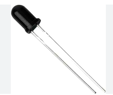
A photodiode is a semiconductor device that converts light into an electrical current. The current is generated when photons are absorbed in the photodiode. Photodiodes are designed to operate in reverse-bias mode, where a voltage is applied in the direction that would normally block current flow. This reverse bias increases the photodiode's sensitivity to light. Photodiodes are commonly used in light sensing applications, including camera light meters, optical communication devices, and light beam alignment.
Explore Projects Built with Photodiode
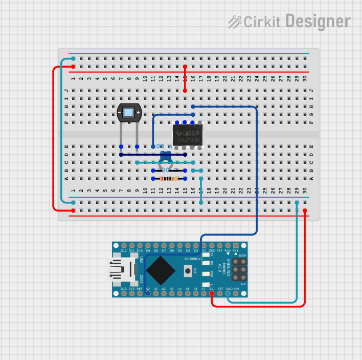
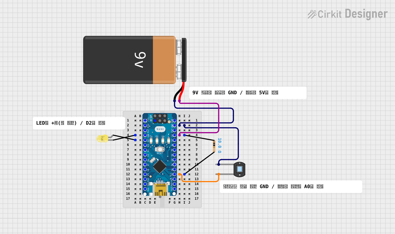
Explore Projects Built with Photodiode
Common Applications and Use Cases
- Light detection and measurement
- Optical communication systems
- Safety and security devices
- Position sensors
- Medical devices
Technical Specifications
Key Technical Details
- Material: Silicon, Germanium, or other semiconductor materials
- Spectral Response: Typically from 200 nm to 1100 nm (varies by material)
- Reverse Voltage: Varies by model (e.g., 5V, 10V, 100V)
- Dark Current: The current through the photodiode in the absence of light; typically in the nanoampere range
- Responsivity: The ratio of the generated photocurrent to the incident light power, typically expressed in A/W
Pin Configuration and Descriptions
| Pin Number | Name | Description |
|---|---|---|
| 1 | Anode | The positive side of the photodiode, typically connected to ground in reverse-bias applications |
| 2 | Cathode | The negative side of the photodiode, typically connected to the positive voltage supply in reverse-bias applications |
Usage Instructions
How to Use the Photodiode in a Circuit
- Reverse Bias Connection: Connect the anode of the photodiode to the ground and the cathode to a positive voltage supply. The voltage should not exceed the maximum reverse voltage rating of the photodiode.
- Current Measurement: The photocurrent can be measured by connecting a resistor in series with the photodiode and measuring the voltage across the resistor.
- Amplification: The photocurrent is typically very small and may require amplification. This can be done using a transimpedance amplifier.
Important Considerations and Best Practices
- Reverse Bias: Ensure the photodiode is always reverse-biased to increase the width of the depletion region, which improves response time and sensitivity.
- Shielding: Photodiodes are sensitive to ambient light. Use appropriate shielding to prevent interference from unwanted light sources.
- Load Resistor: Choose an appropriate value for the load resistor to convert the photocurrent to a measurable voltage without affecting the response time significantly.
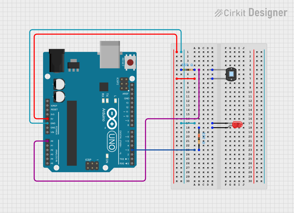
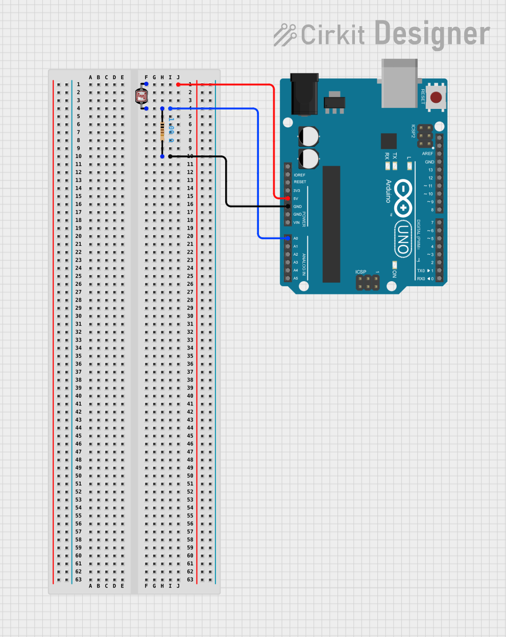
Example Circuit with Arduino UNO
// Define the photodiode pin
const int photodiodePin = A0; // Connect photodiode to analog pin A0

void setup() {
  Serial.begin(9600); // Start serial communication at 9600 baud
}

void loop() {
  int sensorValue = analogRead(photodiodePin); // Read the photodiode value
  float voltage = sensorValue * (5.0 / 1023.0); // Convert to voltage
  Serial.println(voltage); // Print the voltage to the Serial Monitor
  delay(1000); // Wait for 1 second before the next read
}
Troubleshooting and FAQs
Common Issues
- Low Responsivity: If the photodiode seems unresponsive, check if it is properly reverse-biased and that there is no light leakage affecting the readings.
- High Dark Current: A high dark current may indicate a problem with the photodiode or the presence of ambient light. Ensure the photodiode is adequately shielded.
Solutions and Tips for Troubleshooting
- Check Connections: Verify that the photodiode is correctly connected with the anode to ground and the cathode to the positive voltage.
- Ambient Light: Ensure that the photodiode is not exposed to stray light, which can affect the measurements.
- Amplifier Setup: If using an amplifier, ensure that it is correctly configured to handle the small photocurrent.
FAQs
Q: Can I use a photodiode to measure the intensity of light? A: Yes, photodiodes are commonly used to measure light intensity. The photocurrent is proportional to the incident light power.
Q: What is the difference between a photodiode and a phototransistor? A: A phototransistor is similar to a photodiode but with internal amplification. Phototransistors are generally more sensitive than photodiodes but have slower response times.
Q: How can I improve the response time of a photodiode? A: To improve the response time, minimize the capacitance in the circuit by using shorter leads and smaller load resistors, and ensure the photodiode is properly reverse-biased.