How to Use Shunt 75MV/20A: Examples, Pinouts, and Specs
Introduction
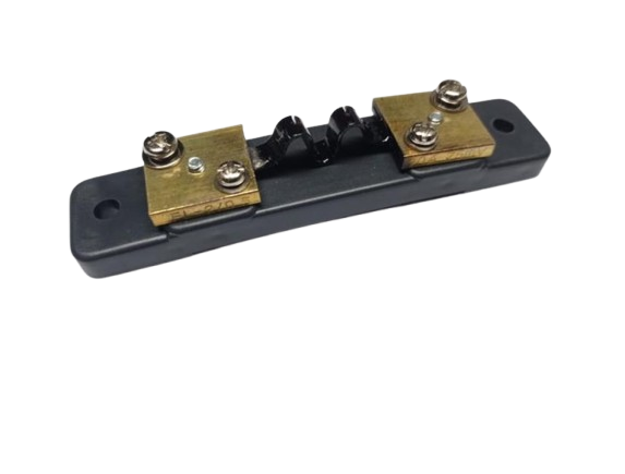
A shunt is a precision resistor designed to measure current by generating a small, proportional voltage drop across its terminals. The Shunt 75MV/20A is specifically calibrated to produce a voltage drop of 75 millivolts (mV) when a current of 20 amperes (A) flows through it. This makes it an ideal component for current measurement in high-power circuits, where direct current measurement is impractical.
Explore Projects Built with Shunt 75MV/20A


Explore Projects Built with Shunt 75MV/20A
Common Applications and Use Cases
- Current measurement in power supply systems
- Battery monitoring and management systems
- Industrial equipment and motor control
- Energy meters and power monitoring devices
- Integration with microcontrollers and data acquisition systems
Technical Specifications
Key Technical Details
- Maximum Current Rating: 20A
- Voltage Drop at Maximum Current: 75mV
- Resistance: 3.75 milliohms (calculated as 75mV / 20A)
- Accuracy: Typically ±0.5% or better
- Material: Manganin or similar low-temperature-coefficient alloy
- Operating Temperature Range: -40°C to +85°C
- Mounting Style: Screw terminals or solderable connections
Pin Configuration and Descriptions
The Shunt 75MV/20A typically has two main terminals for current flow and two smaller terminals for voltage measurement. These are described in the table below:
| Terminal Name | Description |
|---|---|
| Current Input (+) | Connect to the positive side of the current source or load. |
| Current Output (-) | Connect to the negative side of the current source or load. |
| Voltage Sense (+) | Connect to the positive input of a voltmeter or ADC for voltage measurement. |
| Voltage Sense (-) | Connect to the negative input of a voltmeter or ADC for voltage measurement. |
Usage Instructions
How to Use the Shunt in a Circuit
Placement in the Circuit:
- Place the shunt in series with the load whose current you want to measure.
- Ensure the current flows from the Current Input (+) terminal to the Current Output (-) terminal.
Voltage Measurement:
- Use a high-impedance voltmeter or an analog-to-digital converter (ADC) to measure the voltage across the Voltage Sense (+) and Voltage Sense (-) terminals.
- The measured voltage will be proportional to the current flowing through the shunt, based on the formula: [ I = \frac{V}{R} ] where ( I ) is the current, ( V ) is the measured voltage, and ( R ) is the shunt resistance (3.75 milliohms).
Connection to Microcontrollers:
- If using a microcontroller like an Arduino UNO, connect the Voltage Sense (+) terminal to an analog input pin and the Voltage Sense (-) terminal to the ground (GND).
- Use the ADC to read the voltage and calculate the current.
Important Considerations and Best Practices
- Power Dissipation: Ensure the shunt's power dissipation does not exceed its rating. For the Shunt 75MV/20A, the maximum power dissipation is: [ P = I^2 \times R = 20^2 \times 0.00375 = 1.5 , \text{W} ]
- Wiring: Use thick, low-resistance wires for the current-carrying terminals to minimize additional resistance.
- Temperature Effects: Avoid placing the shunt near heat sources, as temperature changes can affect its resistance and accuracy.
- Calibration: Periodically verify the shunt's accuracy using a known current source and a precision voltmeter.
Example Code for Arduino UNO
The following code demonstrates how to measure current using the Shunt 75MV/20A and an Arduino UNO:
// Define the analog pin connected to the Voltage Sense (+) terminal
const int shuntPin = A0;

// Shunt resistance in ohms (3.75 milliohms)
const float shuntResistance = 0.00375;

// ADC reference voltage (5V for Arduino UNO)
const float adcReferenceVoltage = 5.0;

// ADC resolution (10-bit ADC for Arduino UNO)
const int adcResolution = 1024;

void setup() {
  Serial.begin(9600); // Initialize serial communication
}

void loop() {
  // Read the raw ADC value
  int adcValue = analogRead(shuntPin);

  // Convert ADC value to voltage
  float shuntVoltage = (adcValue * adcReferenceVoltage) / adcResolution;

  // Calculate current using Ohm's Law (I = V / R)
  float current = shuntVoltage / shuntResistance;

  // Print the measured current to the Serial Monitor
  Serial.print("Current: ");
  Serial.print(current, 2); // Print current with 2 decimal places
  Serial.println(" A");

  delay(1000); // Wait for 1 second before the next reading
}
Troubleshooting and FAQs
Common Issues and Solutions
No Voltage Reading Across the Shunt:
- Cause: Improper wiring or no current flowing through the shunt.
- Solution: Verify the connections and ensure the shunt is in series with the load.
Inaccurate Current Measurement:
- Cause: High resistance in the wiring or incorrect ADC reference voltage.
- Solution: Use thick wires for current connections and ensure the ADC reference voltage is correctly set in the code.
Overheating of the Shunt:
- Cause: Current exceeds the shunt's maximum rating.
- Solution: Ensure the current does not exceed 20A. Use a higher-rated shunt if necessary.
Fluctuating Readings:
- Cause: Electrical noise or poor connections.
- Solution: Use shielded cables for voltage sense lines and ensure all connections are secure.
FAQs
Q1: Can I use the Shunt 75MV/20A for AC current measurement?
A1: No, this shunt is designed for DC current measurement. For AC, you would need additional circuitry, such as a rectifier and filter.
Q2: What happens if I exceed the 20A current rating?
A2: Exceeding the current rating can cause excessive heat, damage the shunt, and reduce measurement accuracy. Always stay within the specified limits.
Q3: Can I use this shunt with a 3.3V microcontroller?
A3: Yes, but ensure the voltage drop across the shunt does not exceed the ADC input range of the microcontroller. Adjust the code accordingly for the 3.3V reference voltage.
Q4: How do I improve measurement accuracy?
A4: Use a high-resolution ADC, minimize noise in the circuit, and ensure proper calibration of the shunt and measurement system.