
How to Use Garmin LIDAR-Lite v4: Examples, Pinouts, and Specs
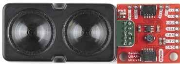
 Design with Garmin LIDAR-Lite v4 in Cirkit Designer
Introduction
The Garmin LIDAR-Lite v4 (Part ID: 010-02022-00) is a compact and lightweight laser rangefinder designed for accurate distance measurements using LIDAR (Light Detection and Ranging) technology. This versatile sensor is ideal for applications such as robotics, drones, automation, and other systems requiring precise distance sensing. Its small form factor and low power consumption make it suitable for both hobbyist and professional projects.
Explore Projects Built with Garmin LIDAR-Lite v4
 Open Project in Cirkit Designer
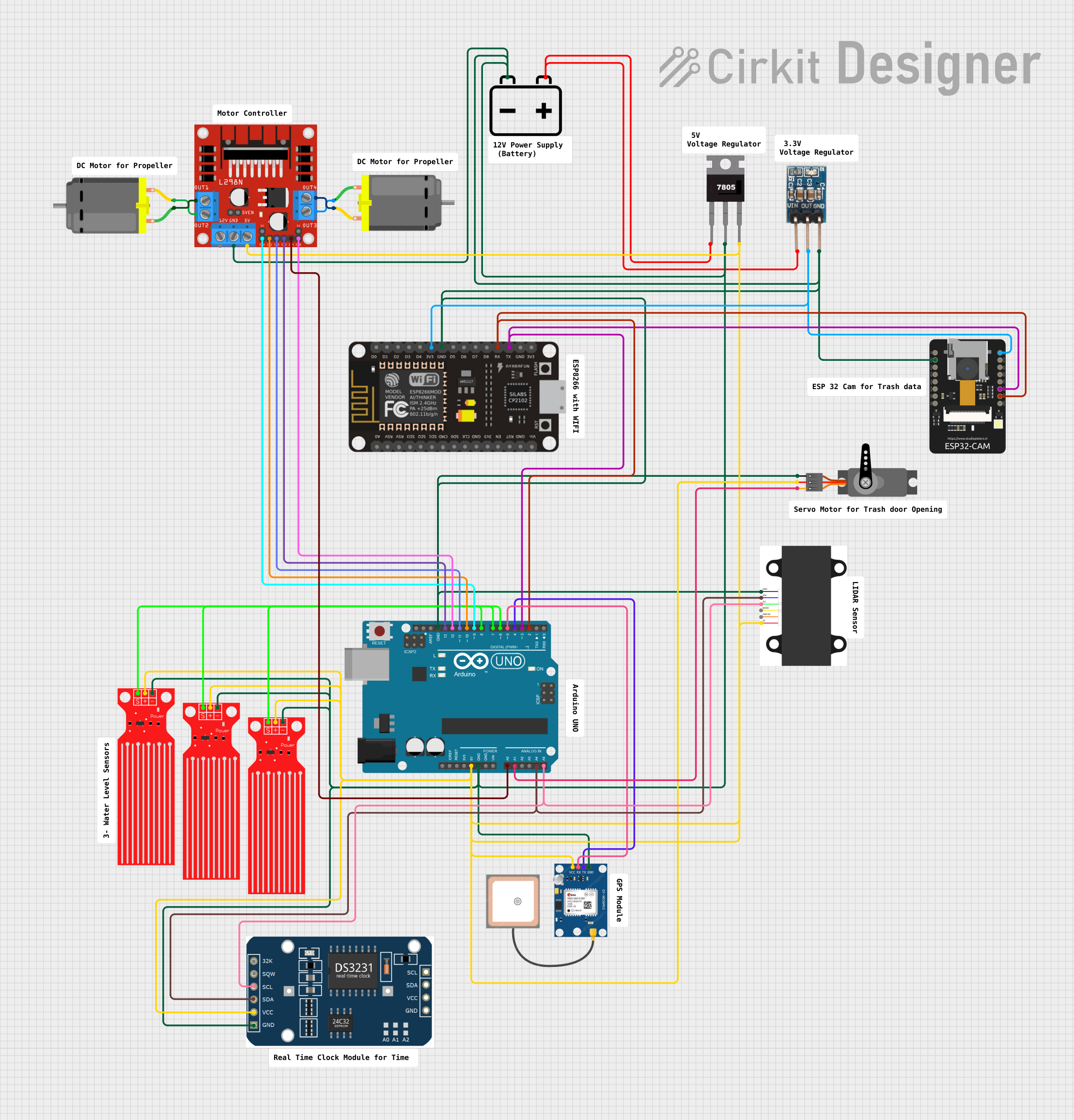 Open Project in Cirkit Designer
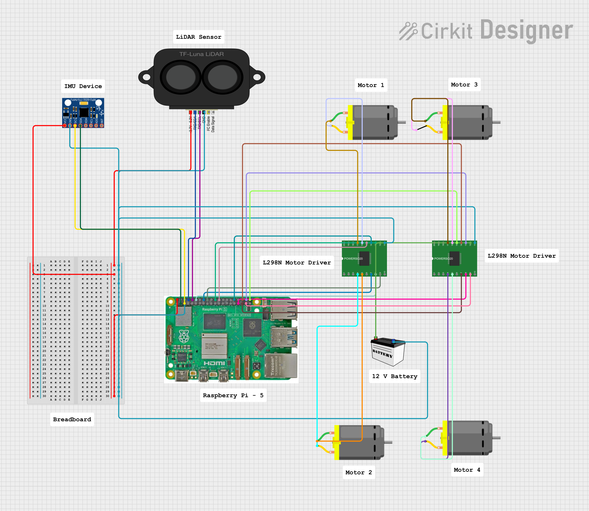 Open Project in Cirkit Designer
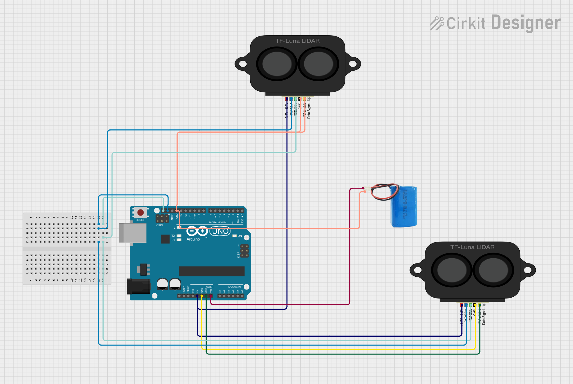 Open Project in Cirkit Designer
Explore Projects Built with Garmin LIDAR-Lite v4
Open Project in Cirkit DesignerOpen Project in Cirkit DesignerOpen Project in Cirkit DesignerOpen Project in Cirkit DesignerCommon Applications
- Obstacle detection and avoidance in robotics and drones
- Terrain mapping and navigation
- Industrial automation and object detection
- Distance measurement in IoT devices
- Educational and research projects
Technical Specifications
The following table outlines the key technical specifications of the Garmin LIDAR-Lite v4:
| Specification | Value |
|---|---|
| Measurement Range | 5 cm to 10 m |
| Accuracy | ±2.5 cm |
| Operating Voltage | 4.75 V to 5.5 V |
| Current Consumption | 85 mA (typical), 130 mA (peak) |
| Interface | I2C or PWM |
| Operating Temperature Range | -20°C to 60°C |
| Dimensions | 53 mm x 33 mm x 21 mm |
| Weight | 10 g |
Pin Configuration
The Garmin LIDAR-Lite v4 features a 6-pin connector for interfacing. The pin configuration is as follows:
| Pin Number | Name | Description |
|---|---|---|
| 1 | GND | Ground |
| 2 | +5V | Power supply (4.75 V to 5.5 V) |
| 3 | MODE | Mode selection (I2C or PWM) |
| 4 | I2C_SCL | I2C clock line |
| 5 | I2C_SDA | I2C data line |
| 6 | PWM_OUT | PWM output for distance measurement |
Usage Instructions
Connecting the LIDAR-Lite v4
- Power Supply: Connect the
+5Vpin to a 5V power source and theGNDpin to ground. - Interface Selection: Use the
MODEpin to select the desired interface:- Leave the
MODEpin unconnected for I2C communication. - Connect the
MODEpin to ground for PWM output.
- Leave the
- I2C Communication:
- Connect the
I2C_SCLpin to the SCL pin of your microcontroller. - Connect the
I2C_SDApin to the SDA pin of your microcontroller.
- Connect the
- PWM Output:
- Connect the
PWM_OUTpin to a digital input pin on your microcontroller to read distance measurements.
- Connect the
Important Considerations
- Ensure the power supply voltage is within the specified range (4.75 V to 5.5 V).
- Avoid exposing the sensor to direct sunlight or reflective surfaces, as this may affect accuracy.
- Use pull-up resistors (typically 4.7 kΩ) on the I2C lines if your microcontroller does not have internal pull-ups.
- Mount the sensor securely to minimize vibrations, which can interfere with measurements.
Example: Using LIDAR-Lite v4 with Arduino UNO (I2C Mode)
Below is an example Arduino sketch to interface the LIDAR-Lite v4 using I2C:
#include <Wire.h> // Include the Wire library for I2C communication

#define LIDAR_ADDRESS 0x62 // Default I2C address for LIDAR-Lite v4
#define MEASURE_REGISTER 0x00 // Register to initiate measurement
#define DISTANCE_REGISTER 0x10 // Register to read distance

void setup() {
  Wire.begin(); // Initialize I2C communication
  Serial.begin(9600); // Start serial communication for debugging
  Serial.println("LIDAR-Lite v4 Initialization...");
}

void loop() {
  // Initiate a measurement
  Wire.beginTransmission(LIDAR_ADDRESS);
  Wire.write(MEASURE_REGISTER); // Write to the measurement register
  Wire.write(0x04); // Command to start measurement
  Wire.endTransmission();

  delay(20); // Wait for measurement to complete

  // Read the distance value
  Wire.beginTransmission(LIDAR_ADDRESS);
  Wire.write(DISTANCE_REGISTER); // Set register pointer to distance register
  Wire.endTransmission(false); // Restart I2C communication

  Wire.requestFrom(LIDAR_ADDRESS, 2); // Request 2 bytes of data
  if (Wire.available() == 2) {
    uint16_t distance = Wire.read() << 8; // Read high byte
    distance |= Wire.read(); // Read low byte
    Serial.print("Distance: ");
    Serial.print(distance);
    Serial.println(" cm");
  }

  delay(100); // Delay before the next measurement
}
Notes:
- Ensure the LIDAR-Lite v4 is connected to the correct I2C pins on the Arduino UNO (
A4for SDA andA5for SCL). - Use a logic level shifter if your microcontroller operates at 3.3V logic levels.
Troubleshooting and FAQs
Common Issues
No Response from the Sensor:
- Verify the power supply voltage and connections.
- Check the I2C address (default is
0x62) and ensure no address conflicts. - Ensure pull-up resistors are present on the I2C lines.
Inaccurate Measurements:
- Avoid reflective or transparent surfaces in the sensor's field of view.
- Ensure the sensor is mounted securely to reduce vibrations.
PWM Output Not Working:
- Confirm the
MODEpin is connected to ground. - Verify the microcontroller's digital input pin configuration.
- Confirm the
FAQs
Q: Can the LIDAR-Lite v4 measure distances beyond 10 meters?
A: No, the maximum measurement range is 10 meters. For longer ranges, consider other LIDAR models.
Q: Is the sensor compatible with 3.3V microcontrollers?
A: Yes, but you must use a logic level shifter for the I2C lines to avoid damaging the sensor.
Q: How can I reduce measurement noise?
A: Use averaging techniques in your code and ensure the sensor is not exposed to excessive vibrations or environmental interference.
Q: Can I use multiple LIDAR-Lite v4 sensors on the same I2C bus?
A: Yes, but you must configure each sensor with a unique I2C address. Refer to the sensor's datasheet for instructions on changing the address.