How to Use optocoupler pc817 4 channel: Examples, Pinouts, and Specs
Introduction
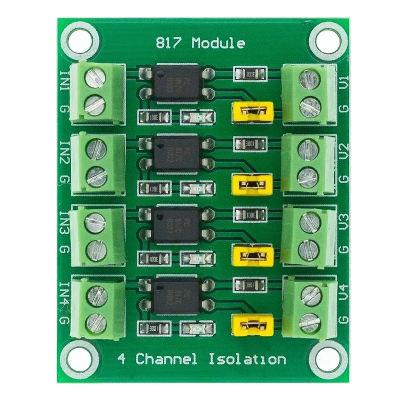
The PC817 is a 4-channel optocoupler designed to provide electrical isolation between its input and output. Each channel consists of an infrared LED and a phototransistor, enabling signal transmission without direct electrical connection. This isolation is crucial for protecting sensitive components, such as microcontrollers, from high-voltage circuits or noisy environments.
Explore Projects Built with optocoupler pc817 4 channel


Explore Projects Built with optocoupler pc817 4 channel
Common Applications and Use Cases
- Signal isolation in microcontroller-based systems
- Interfacing low-voltage logic circuits with high-voltage devices
- Noise suppression in industrial control systems
- Protection of sensitive electronics from voltage spikes
- AC/DC power supply feedback circuits
Technical Specifications
The PC817 4-channel optocoupler has the following key technical details:
| Parameter | Value |
|---|---|
| Channels | 4 |
| Input Type | Infrared LED |
| Output Type | Phototransistor |
| Isolation Voltage | 5,000 Vrms (minimum) |
| Forward Voltage (LED) | 1.2V (typical), 1.4V (maximum) |
| Forward Current (LED) | 20mA (maximum) |
| Collector-Emitter Voltage | 35V (maximum) |
| Current Transfer Ratio (CTR) | 50% to 600% (depending on model) |
| Operating Temperature Range | -30°C to +100°C |
| Package Type | DIP-16 |
Pin Configuration and Descriptions
The PC817 4-channel optocoupler is housed in a 16-pin DIP package. The pin configuration is as follows:
| Pin Number | Name | Description |
|---|---|---|
| 1, 3, 5, 7 | Anode (Input) | Positive terminal of the LED for each channel. |
| 2, 4, 6, 8 | Cathode (Input) | Negative terminal of the LED for each channel. |
| 9, 11, 13, 15 | Emitter (Output) | Emitter terminal of the phototransistor for each channel. |
| 10, 12, 14, 16 | Collector (Output) | Collector terminal of the phototransistor for each channel. |
Usage Instructions
How to Use the PC817 in a Circuit
Connect the Input Side (LED):
- Connect the anode (positive terminal) of the LED to the signal source.
- Use a current-limiting resistor in series with the LED to prevent overcurrent. Calculate the resistor value using Ohm's law:
[ R = \frac{V_{in} - V_f}{I_f} ]
Where (V_{in}) is the input voltage, (V_f) is the forward voltage of the LED (1.2V typical), and (I_f) is the desired forward current (e.g., 10mA).
Connect the Output Side (Phototransistor):
- Connect the collector to the positive supply voltage (e.g., 5V or 3.3V).
- Connect the emitter to ground through a pull-down resistor. The resistor value determines the output voltage level and response time.
Verify Isolation:
- Ensure there is no direct electrical connection between the input and output sides.
Important Considerations and Best Practices
- Current Transfer Ratio (CTR): The CTR determines the efficiency of signal transfer. Choose a PC817 variant with a suitable CTR for your application.
- Input Current: Do not exceed the maximum forward current (20mA) to avoid damaging the LED.
- Output Voltage: Ensure the collector-emitter voltage does not exceed 35V.
- Temperature: Operate the component within the specified temperature range (-30°C to +100°C).
- PCB Layout: Maintain sufficient spacing between input and output traces to preserve isolation.
Example: Interfacing with an Arduino UNO
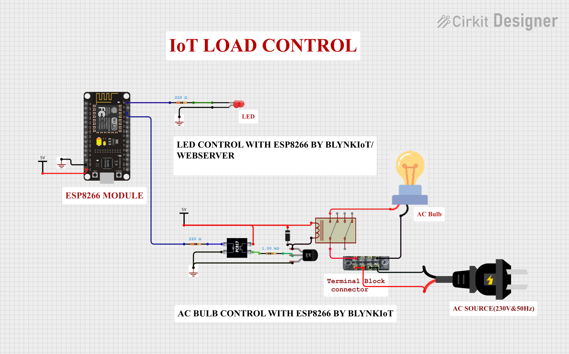
Below is an example of how to use the PC817 to interface a 5V Arduino UNO with a 12V relay:
Circuit Connections
- Input Side:
- Connect the anode of the PC817 LED to an Arduino digital pin (e.g., D2) through a 330Ω resistor.
- Connect the cathode of the LED to Arduino GND.
- Output Side:
- Connect the collector of the phototransistor to the 12V relay's control pin.
- Connect the emitter to GND through a 10kΩ pull-down resistor.
Arduino Code
// Example code to control a relay using the PC817 optocoupler

const int optoPin = 2; // Arduino pin connected to the PC817 input

void setup() {
  pinMode(optoPin, OUTPUT); // Set the optoPin as an output
}

void loop() {
  digitalWrite(optoPin, HIGH); // Turn on the optocoupler (relay ON)
  delay(1000);                // Wait for 1 second
  digitalWrite(optoPin, LOW); // Turn off the optocoupler (relay OFF)
  delay(1000);                // Wait for 1 second
}
Troubleshooting and FAQs
Common Issues and Solutions
LED Not Lighting Up:
- Cause: Insufficient input current or incorrect resistor value.
- Solution: Verify the resistor value and ensure the input voltage is sufficient.
No Output Signal:
- Cause: Incorrect wiring on the output side or damaged phototransistor.
- Solution: Check the collector-emitter connections and ensure the pull-down resistor is properly connected.
Signal Distortion or Noise:
- Cause: High-speed switching or insufficient pull-down resistance.
- Solution: Use a lower-value pull-down resistor or add a capacitor across the output to filter noise.
Component Overheating:
- Cause: Exceeding the maximum current or voltage ratings.
- Solution: Ensure the input current and output voltage are within the specified limits.
FAQs
Q: Can the PC817 be used for AC signal isolation?
A: Yes, the PC817 can isolate AC signals, but you must use a rectifier circuit to convert the AC signal to DC for the LED input.
Q: What is the maximum switching speed of the PC817?
A: The PC817 has a typical switching time of 3-4µs, making it suitable for low- to medium-speed applications.
Q: Can I use the PC817 with a 3.3V microcontroller?
A: Yes, the PC817 can operate with a 3.3V input, but ensure the forward current of the LED is sufficient by selecting an appropriate resistor value.