
How to Use INVERTING_SCHMITT_TRIGGER: Examples, Pinouts, and Specs
 Design with INVERTING_SCHMITT_TRIGGER in Cirkit Designer
Introduction
The INVERTING SCHMITT TRIGGER (Manufacturer Part ID: NC7SZ14M5X) by onsemi is a compact and efficient comparator circuit designed to provide hysteresis. This feature ensures clean and stable transitions between high and low states, even in the presence of noisy or slow-changing input signals. The component inverts the input signal, making it ideal for applications requiring signal conditioning, noise elimination, and waveform shaping.
Explore Projects Built with INVERTING_SCHMITT_TRIGGER
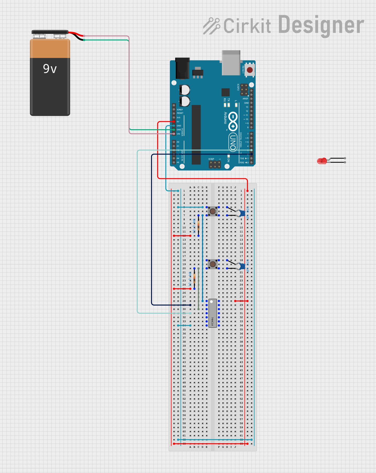 Open Project in Cirkit Designer
 Open Project in Cirkit Designer
 Open Project in Cirkit Designer
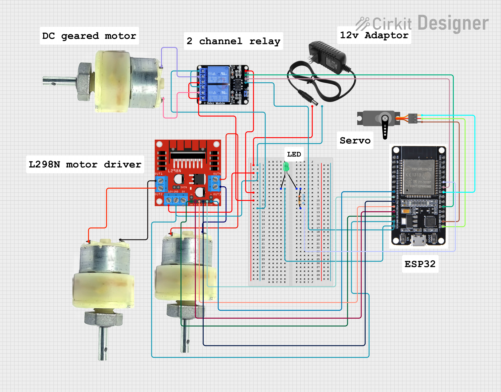 Open Project in Cirkit Designer
Explore Projects Built with INVERTING_SCHMITT_TRIGGER
Open Project in Cirkit DesignerOpen Project in Cirkit DesignerOpen Project in Cirkit DesignerOpen Project in Cirkit DesignerCommon Applications and Use Cases
- Signal noise filtering in digital circuits
- Waveform shaping and signal restoration
- Debouncing mechanical switches
- Pulse generation and timing circuits
- Interfacing slow analog signals with digital systems
Technical Specifications
Key Technical Details
- Supply Voltage (Vcc): 1.65V to 5.5V
- Input Voltage Range: 0V to Vcc
- Output Voltage Range: 0V to Vcc
- Hysteresis Voltage (Vh): ~0.4V (typical at Vcc = 5V)
- Propagation Delay: ~3.5ns (typical at Vcc = 5V)
- Output Drive Current: ±24mA (maximum)
- Operating Temperature Range: -40°C to +125°C
- Package Type: SOT-23-5 (5-pin)
Pin Configuration and Descriptions
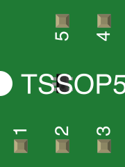
The NC7SZ14M5X is housed in a 5-pin SOT-23 package. The pinout and descriptions are as follows:
| Pin Number | Pin Name | Description |
|---|---|---|
| 1 | GND | Ground (0V reference) |
| 2 | IN | Input signal to the Schmitt Trigger |
| 3 | OUT | Inverted output signal |
| 4 | NC | No connection (leave unconnected) |
| 5 | Vcc | Positive supply voltage |
Usage Instructions
How to Use the Component in a Circuit
Power Supply:
- Connect the Vcc pin to a stable DC voltage source within the range of 1.65V to 5.5V.
- Connect the GND pin to the ground of the circuit.
Input Signal:
- Apply the input signal to the IN pin. Ensure the signal voltage stays within the range of 0V to Vcc.
- The Schmitt Trigger will invert the input signal and apply hysteresis to eliminate noise.
Output Signal:
- The inverted and noise-filtered signal will be available at the OUT pin.
- The output can directly drive digital logic circuits or LEDs (with a current-limiting resistor).
Important Considerations and Best Practices
- Decoupling Capacitor: Place a 0.1µF ceramic capacitor close to the Vcc and GND pins to filter out power supply noise.
- Input Signal Levels: Ensure the input signal transitions through the hysteresis range for proper operation.
- Unused Pins: Leave the NC pin unconnected.
- Output Loading: Avoid exceeding the maximum output current rating (±24mA) to prevent damage.
Example: Using with Arduino UNO
The NC7SZ14M5X can be used with an Arduino UNO to debounce a mechanical switch. Below is an example circuit and code:
Circuit Setup
- Connect the switch between the input pin (IN) and ground.
- Use a pull-up resistor (e.g., 10kΩ) between the input pin and Vcc.
- Connect the OUT pin to a digital input pin on the Arduino (e.g., D2).
Arduino Code
// Example code for using NC7SZ14M5X with Arduino UNO
const int inputPin = 2;  // Digital pin connected to OUT of Schmitt Trigger
const int ledPin = 13;   // Onboard LED pin

void setup() {
  pinMode(inputPin, INPUT);  // Set inputPin as input
  pinMode(ledPin, OUTPUT);   // Set ledPin as output
  Serial.begin(9600);        // Initialize serial communication
}

void loop() {
  int state = digitalRead(inputPin);  // Read the Schmitt Trigger output
  digitalWrite(ledPin, state);        // Reflect the state on the LED
  Serial.println(state);              // Print the state to the Serial Monitor
  delay(100);                         // Small delay for stability
}
Troubleshooting and FAQs
Common Issues and Solutions
No Output Signal:
- Verify that the power supply is connected correctly to the Vcc and GND pins.
- Ensure the input signal transitions through the hysteresis range.
Output Signal is Not Inverted:
- Check the input signal polarity and ensure it is within the specified voltage range.
- Confirm that the component is not damaged.
Excessive Noise on Output:
- Add a decoupling capacitor (0.1µF) near the power supply pins.
- Ensure proper grounding and minimize noise in the input signal.
Component Overheating:
- Verify that the output current does not exceed ±24mA.
- Check for short circuits or incorrect wiring.
FAQs
Q1: Can the NC7SZ14M5X handle analog signals?
A1: Yes, it can process slow-changing analog signals, but the output will always be a digital signal (high or low) due to the Schmitt Trigger's nature.
Q2: What happens if the input signal does not cross the hysteresis threshold?
A2: The output will remain in its current state until the input signal crosses the threshold.
Q3: Can I use this component for high-speed applications?
A3: Yes, the NC7SZ14M5X has a fast propagation delay (~3.5ns at Vcc = 5V), making it suitable for high-speed digital circuits.
Q4: Is it possible to cascade multiple Schmitt Triggers?
A4: Yes, you can cascade them for additional signal conditioning or to create more complex logic circuits.