
How to Use Matek Optical Flow & LIDAR Sensor: Examples, Pinouts, and Specs
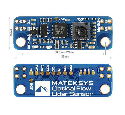
 Design with Matek Optical Flow & LIDAR Sensor in Cirkit Designer
Introduction
The Matek Optical Flow & LIDAR Sensor is a versatile and compact module that combines optical flow technology with LIDAR-based distance measurement. This dual-functionality sensor is designed to provide precise motion tracking and accurate distance measurements, making it an ideal choice for applications in drones, robotics, and autonomous navigation systems. By integrating optical flow for horizontal motion detection and LIDAR for vertical distance sensing, this sensor ensures reliable performance in dynamic environments.
Explore Projects Built with Matek Optical Flow & LIDAR Sensor
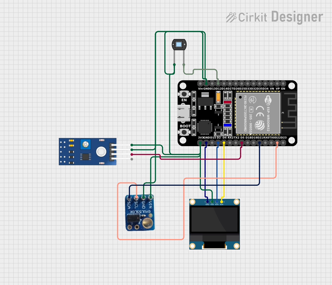 Open Project in Cirkit Designer
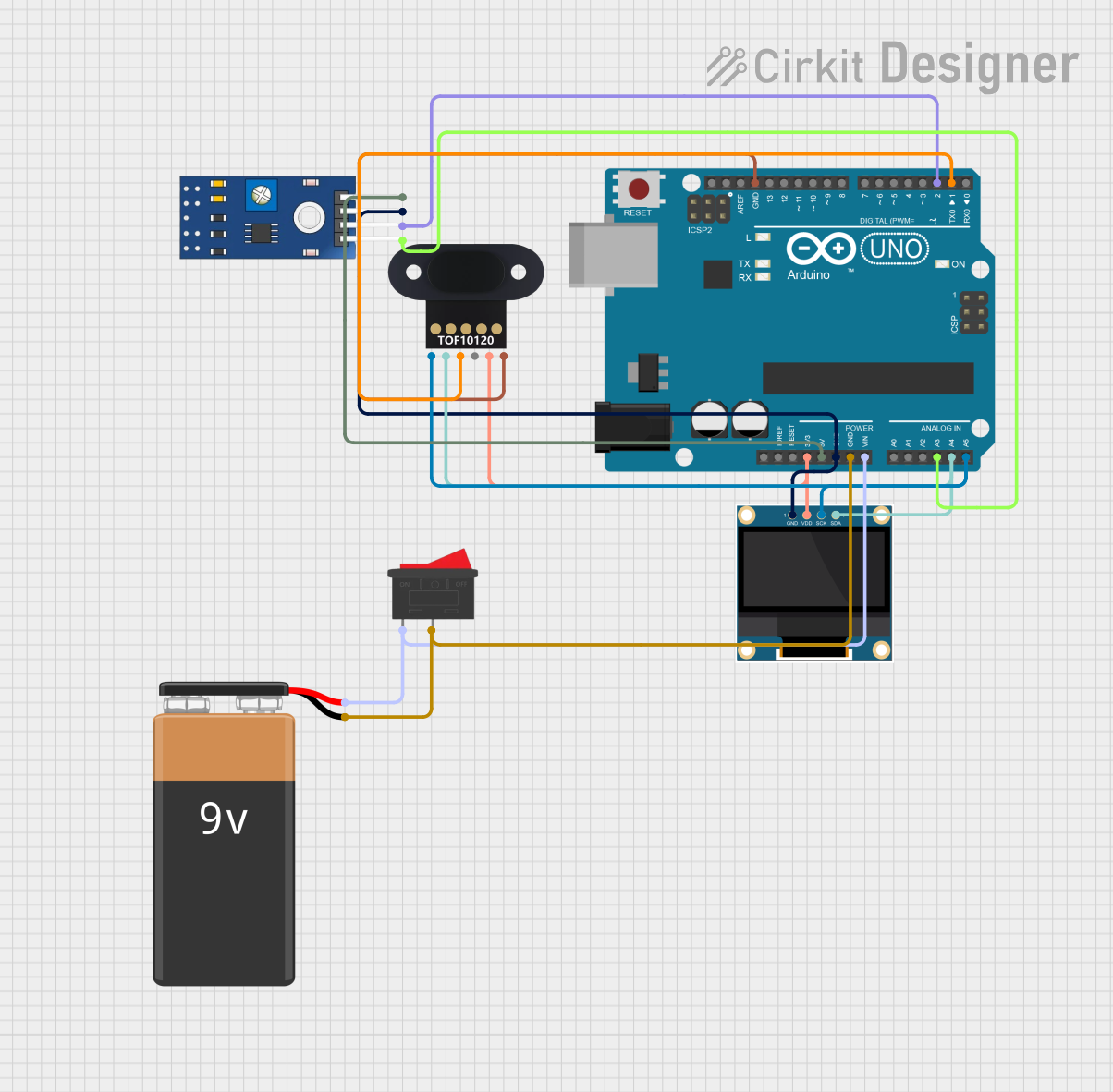 Open Project in Cirkit Designer
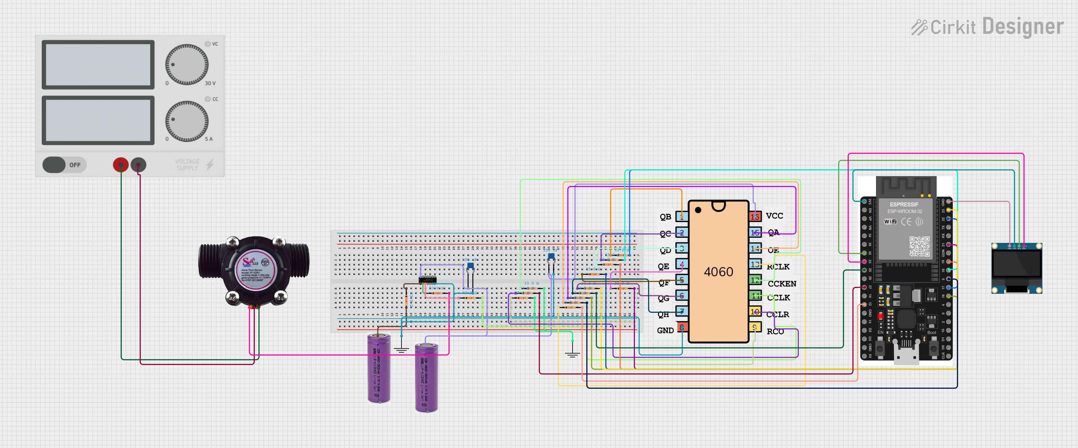 Open Project in Cirkit Designer
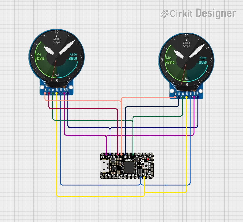 Open Project in Cirkit Designer
Explore Projects Built with Matek Optical Flow & LIDAR Sensor
Open Project in Cirkit DesignerOpen Project in Cirkit DesignerOpen Project in Cirkit DesignerOpen Project in Cirkit DesignerCommon Applications and Use Cases
- Autonomous drones for stable hovering and navigation
- Robotics for obstacle detection and avoidance
- Indoor navigation systems
- Terrain-following applications
- Precision landing systems for UAVs
Technical Specifications
The following table outlines the key technical specifications of the Matek Optical Flow & LIDAR Sensor:
| Parameter | Specification |
|---|---|
| Manufacturer Part ID | Optical Flow & LIDAR Sensor |
| Operating Voltage | 4.5V to 5.5V |
| Current Consumption | 100mA (typical) |
| Communication Interface | I2C, UART |
| Optical Flow Resolution | 30 x 30 pixels |
| LIDAR Measurement Range | 0.1m to 4m |
| LIDAR Accuracy | ±2% |
| Operating Temperature Range | -10°C to 60°C |
| Dimensions | 25mm x 25mm x 10mm |
| Weight | 5g |
Pin Configuration and Descriptions
The Matek Optical Flow & LIDAR Sensor features a 6-pin connector. The pinout is described in the table below:
| Pin | Name | Description |
|---|---|---|
| 1 | VCC | Power supply input (4.5V to 5.5V) |
| 2 | GND | Ground connection |
| 3 | SDA | I2C data line |
| 4 | SCL | I2C clock line |
| 5 | TX | UART transmit line |
| 6 | RX | UART receive line |
Usage Instructions
How to Use the Component in a Circuit
- Power Supply: Connect the VCC pin to a 5V power source and the GND pin to the ground.
- Communication Interface: Choose between I2C or UART for communication:
- For I2C, connect the SDA and SCL pins to the corresponding pins on your microcontroller.
- For UART, connect the TX and RX pins to the UART pins on your microcontroller.
- Mounting: Secure the sensor to your device, ensuring the optical flow camera faces downward and the LIDAR sensor is unobstructed.
- Initialization: Configure the sensor using the appropriate communication protocol and initialize it in your code.
Important Considerations and Best Practices
- Ensure the sensor is mounted on a stable platform to minimize vibrations, which can affect optical flow accuracy.
- Avoid exposing the sensor to direct sunlight or reflective surfaces, as these can interfere with LIDAR measurements.
- Use pull-up resistors (typically 4.7kΩ) on the SDA and SCL lines if your microcontroller does not have internal pull-ups.
- Maintain a clear line of sight for the LIDAR sensor to ensure accurate distance measurements.
Example Code for Arduino UNO (I2C Communication)
#include <Wire.h>

// I2C address of the Matek Optical Flow & LIDAR Sensor
#define SENSOR_I2C_ADDRESS 0x42

void setup() {
  Wire.begin(); // Initialize I2C communication
  Serial.begin(9600); // Initialize serial communication for debugging

  // Send initialization command to the sensor
  Wire.beginTransmission(SENSOR_I2C_ADDRESS);
  Wire.write(0x00); // Example command to initialize the sensor
  Wire.endTransmission();

  Serial.println("Sensor initialized.");
}

void loop() {
  Wire.beginTransmission(SENSOR_I2C_ADDRESS);
  Wire.write(0x01); // Example command to request data
  Wire.endTransmission();

  Wire.requestFrom(SENSOR_I2C_ADDRESS, 4); // Request 4 bytes of data
  if (Wire.available() == 4) {
    int16_t flowX = Wire.read() << 8 | Wire.read(); // Optical flow X-axis
    int16_t flowY = Wire.read() << 8 | Wire.read(); // Optical flow Y-axis

    Serial.print("Flow X: ");
    Serial.print(flowX);
    Serial.print(", Flow Y: ");
    Serial.println(flowY);
  }

  delay(100); // Delay for stability
}
Troubleshooting and FAQs
Common Issues and Solutions
Sensor Not Responding
- Cause: Incorrect wiring or power supply.
- Solution: Double-check the connections and ensure the sensor is powered with 5V.
Inaccurate Distance Measurements
- Cause: Obstructions or reflective surfaces in the LIDAR's path.
- Solution: Ensure the LIDAR sensor has a clear line of sight and avoid reflective surfaces.
Optical Flow Data is Unstable
- Cause: Excessive vibrations or poor lighting conditions.
- Solution: Mount the sensor on a vibration-dampening platform and ensure adequate lighting.
I2C Communication Fails
- Cause: Missing pull-up resistors or incorrect I2C address.
- Solution: Add pull-up resistors to the SDA and SCL lines and verify the sensor's I2C address.
FAQs
Q: Can the sensor be used outdoors?
A: Yes, but avoid direct sunlight and reflective surfaces, as they can interfere with the sensor's performance.
Q: What is the maximum range of the LIDAR sensor?
A: The LIDAR sensor has a maximum range of 4 meters with an accuracy of ±2%.
Q: Can I use both I2C and UART simultaneously?
A: No, you must choose one communication protocol at a time.
Q: Is the sensor compatible with 3.3V microcontrollers?
A: The sensor requires a 5V power supply, but its I2C and UART lines are 3.3V logic compatible.