How to Use From 2.5-15V to 3.3V buck-boost: Examples, Pinouts, and Specs
Introduction
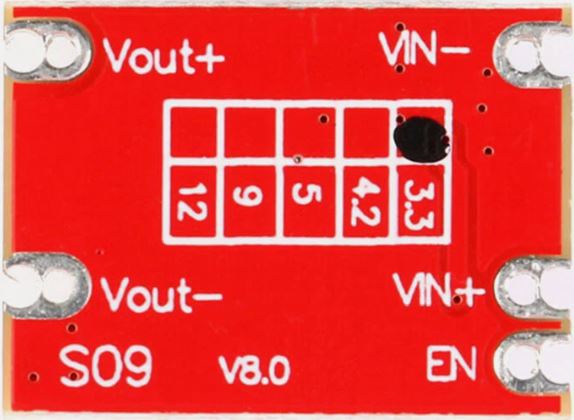
The From 2.5-15V to 3.3V Buck-Boost Converter is a versatile DC-DC converter designed to provide a stable 3.3V output from a wide input voltage range of 2.5V to 15V. This component is ideal for applications where the input voltage may fluctuate above or below the desired output voltage, such as battery-powered devices or systems with varying power sources.
Explore Projects Built with From 2.5-15V to 3.3V buck-boost


Explore Projects Built with From 2.5-15V to 3.3V buck-boost
Common Applications and Use Cases
- Powering microcontrollers, sensors, and low-power devices requiring 3.3V.
- Battery-powered systems where the input voltage drops as the battery discharges.
- Devices requiring a stable 3.3V output from USB, solar panels, or other variable power sources.
- Portable electronics and IoT devices.
Technical Specifications
The following table outlines the key technical details of the buck-boost converter:
| Parameter | Value |
|---|---|
| Input Voltage Range | 2.5V to 15V |
| Output Voltage | 3.3V (fixed) |
| Output Current | Up to 1A (depending on input) |
| Efficiency | Up to 90% (typical) |
| Switching Frequency | 1 MHz (typical) |
| Operating Temperature | -40°C to +85°C |
| Package Type | SMD or DIP (varies by model) |
Pin Configuration and Descriptions
The pinout for the buck-boost converter is as follows:
| Pin | Name | Description |
|---|---|---|
| 1 | VIN | Input voltage pin. Connect to the power source (2.5V to 15V). |
| 2 | GND | Ground pin. Connect to the ground of the circuit. |
| 3 | VOUT | Output voltage pin. Provides a stable 3.3V output. |
| 4 | EN (optional) | Enable pin. Pull high to enable the converter, or low to disable it (if present). |
Usage Instructions
How to Use the Component in a Circuit
Connect the Input Voltage (VIN):
Attach the input voltage source (e.g., battery, USB, or solar panel) to the VIN pin. Ensure the input voltage is within the 2.5V to 15V range.Connect the Ground (GND):
Connect the GND pin to the ground of your circuit.Connect the Output Voltage (VOUT):
Attach the device or circuit requiring 3.3V to the VOUT pin. Ensure the load does not exceed the maximum output current (1A).Enable the Converter (if applicable):
If the converter includes an EN (enable) pin, pull it high (e.g., connect to VIN) to activate the converter. Pull it low to disable the output.
Important Considerations and Best Practices
- Input Capacitor: Place a capacitor (e.g., 10µF) close to the VIN pin to stabilize the input voltage and reduce noise.
- Output Capacitor: Use a capacitor (e.g., 22µF) near the VOUT pin to ensure stable output voltage and minimize ripple.
- Heat Dissipation: Ensure adequate ventilation or heat sinking if the converter operates near its maximum current rating.
- Load Requirements: Verify that the connected load does not exceed the converter's maximum output current.
Example: Using with an Arduino UNO
The buck-boost converter can be used to power an Arduino UNO from a battery or other variable power source. Below is an example circuit and code:
Circuit Connections
- Connect the battery (e.g., 3.7V Li-ion) to the VIN and GND pins of the converter.
- Connect the VOUT pin of the converter to the 3.3V pin of the Arduino UNO.
- Connect the GND pin of the converter to the GND pin of the Arduino UNO.
Example Code
// Example code to read an analog sensor powered by the buck-boost converter
// and print the readings to the Serial Monitor.

const int sensorPin = A0; // Analog pin connected to the sensor
int sensorValue = 0;      // Variable to store the sensor reading

void setup() {
  Serial.begin(9600); // Initialize serial communication at 9600 baud
}

void loop() {
  sensorValue = analogRead(sensorPin); // Read the sensor value
  Serial.print("Sensor Value: ");
  Serial.println(sensorValue); // Print the sensor value to the Serial Monitor
  delay(1000); // Wait for 1 second before the next reading
}
Troubleshooting and FAQs
Common Issues and Solutions
No Output Voltage:
- Cause: The EN pin is not connected or pulled low.
- Solution: Ensure the EN pin is pulled high or connected to VIN.
Output Voltage is Unstable:
- Cause: Insufficient input or output capacitance.
- Solution: Add capacitors (e.g., 10µF at VIN and 22µF at VOUT) close to the pins.
Excessive Heat:
- Cause: The load exceeds the maximum current rating, or poor ventilation.
- Solution: Reduce the load or improve heat dissipation with a heatsink or airflow.
Low Efficiency:
- Cause: Input voltage is too close to the output voltage.
- Solution: Ensure the input voltage is sufficiently different from 3.3V for optimal efficiency.
FAQs
Q1: Can this converter power a 3.3V microcontroller directly?
A1: Yes, as long as the microcontroller's current requirements do not exceed the converter's maximum output current (1A).
Q2: What happens if the input voltage drops below 2.5V?
A2: The converter may shut down or fail to maintain a stable 3.3V output.
Q3: Can I use this converter with a 12V car battery?
A3: Yes, the converter can step down 12V to 3.3V, provided the current draw does not exceed 1A.
Q4: Is the EN pin required for operation?
A4: No, if the EN pin is not used, it can typically be left floating or tied to VIN to enable the converter. Check the specific datasheet for details.