Cirkit Designer Logo
Cirkit Designer
Your all-in-one circuit design IDE
Home / 
Component Documentation

How to Use ESP 32 DEVKIT V1 (30 pins): Examples, Pinouts, and Specs

Image of ESP 32 DEVKIT V1 (30 pins)
Cirkit Designer LogoDesign with ESP 32 DEVKIT V1 (30 pins) in Cirkit Designer

Introduction

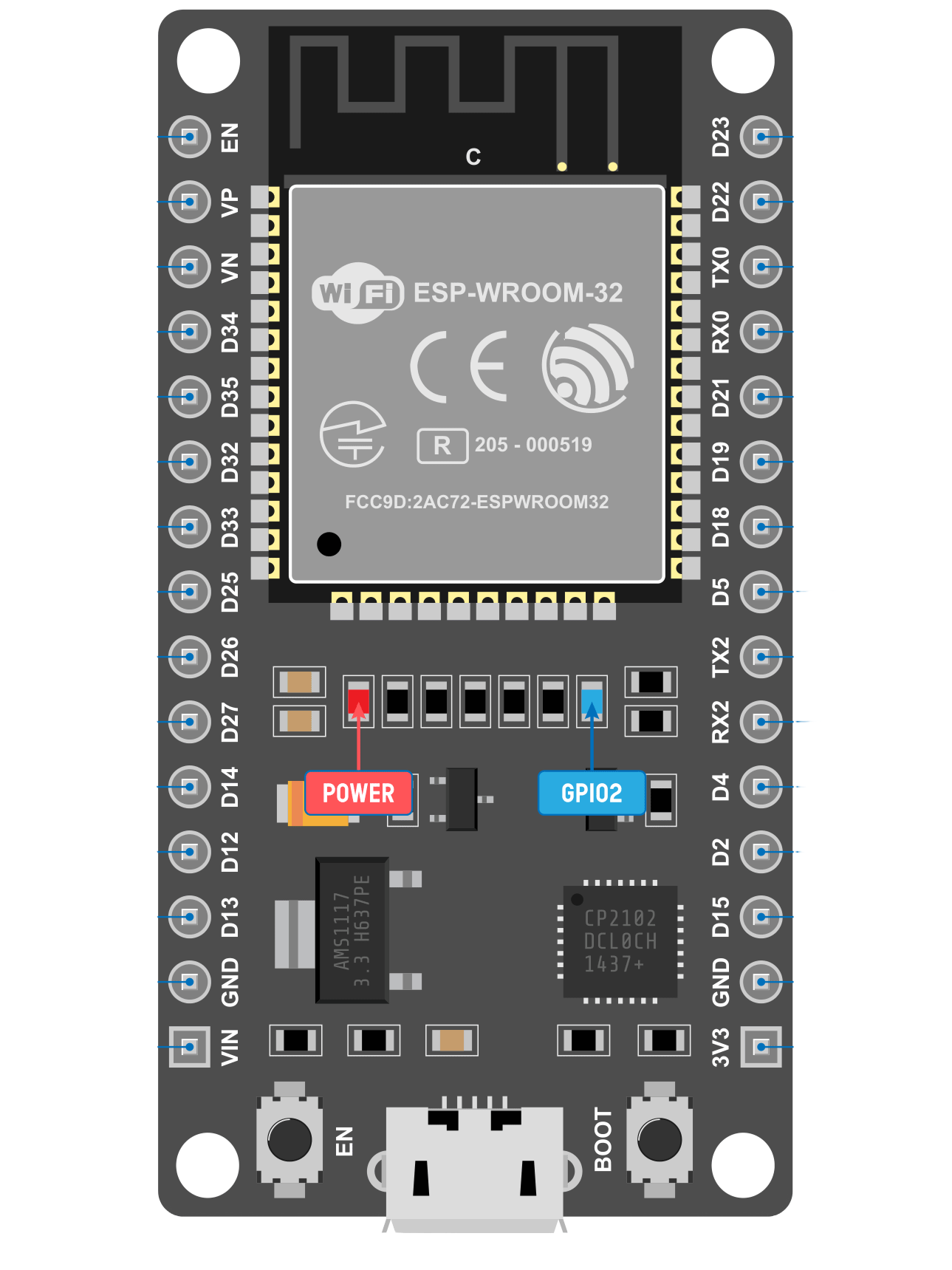
The ESP32 DEVKIT V1 is a versatile development board that harnesses the power of the ESP32 microcontroller. This chip comes with integrated Wi-Fi and Bluetooth capabilities, making it an ideal choice for Internet of Things (IoT) projects. The board's 30 GPIO pins offer a wide range of functionality, from digital and analog I/O to touch sensors, SPI, I2C, and UART communication.

Explore Projects Built with ESP 32 DEVKIT V1 (30 pins)

Use Cirkit Designer to design, explore, and prototype these projects online. Some projects support real-time simulation. Click "Open Project" to start designing instantly!
ESP32 and Logic Level Converter-Based Wi-Fi Controlled Interface
Image of Toshiba AC ESP32 devkit v1: A project utilizing ESP 32 DEVKIT V1 (30 pins) in a practical application
This circuit features an ESP32 Devkit V1 microcontroller connected to a Bi-Directional Logic Level Converter, which facilitates voltage level shifting between the ESP32 and external components. The ESP32 is powered through its VIN pin via an alligator clip cable, and the logic level converter is connected to various pins on the ESP32 to manage different voltage levels for communication.
Cirkit Designer LogoOpen Project in Cirkit Designer
Battery-Powered ESP32 Data Logger with Oscilloscope Monitoring
Image of electromiografia: A project utilizing ESP 32 DEVKIT V1 (30 pins) in a practical application
This circuit features an ESP32 microcontroller powered by a 7V battery, with its ground connected to a common ground. The ESP32's D35 pin is monitored by a mixed signal oscilloscope, and an alligator clip cable is used to connect the oscilloscope's second channel to the common ground.
Cirkit Designer LogoOpen Project in Cirkit Designer
ESP32-Based Environmental Monitoring System with Water Flow Sensing
Image of Water: A project utilizing ESP 32 DEVKIT V1 (30 pins) in a practical application
This circuit features an ESP32 Devkit V1 microcontroller connected to a DHT22 temperature and humidity sensor and a water flow sensor. The ESP32 reads environmental data from the DHT22 via a digital input pin (D33) and monitors water flow through the water flow sensor connected to another digital input pin (D23). The ESP32 is powered through its VIN pin, and both sensors are powered by the ESP32's 3V3 output, with common ground connections.
Cirkit Designer LogoOpen Project in Cirkit Designer
ESP32-Based Smart Agriculture System with LoRa Communication
Image of Soil Monitoring Device: A project utilizing ESP 32 DEVKIT V1 (30 pins) in a practical application
This circuit features an ESP32 Devkit V1 microcontroller as the central processing unit, interfacing with various sensors including a PH Meter, an NPK Soil Sensor, and a Soil Moisture Sensor for environmental data collection. It also includes an EBYTE LoRa E220 module for wireless communication. Power management is handled by a Step Up Boost Power Converter, which is connected to a 12V Battery, stepping up the voltage to power the ESP32 and sensors, with common ground connections throughout the circuit.
Cirkit Designer LogoOpen Project in Cirkit Designer

Explore Projects Built with ESP 32 DEVKIT V1 (30 pins)

Use Cirkit Designer to design, explore, and prototype these projects online. Some projects support real-time simulation. Click "Open Project" to start designing instantly!
Image of Toshiba AC ESP32 devkit v1: A project utilizing ESP 32 DEVKIT V1 (30 pins) in a practical application
ESP32 and Logic Level Converter-Based Wi-Fi Controlled Interface
This circuit features an ESP32 Devkit V1 microcontroller connected to a Bi-Directional Logic Level Converter, which facilitates voltage level shifting between the ESP32 and external components. The ESP32 is powered through its VIN pin via an alligator clip cable, and the logic level converter is connected to various pins on the ESP32 to manage different voltage levels for communication.
Cirkit Designer LogoOpen Project in Cirkit Designer
Image of electromiografia: A project utilizing ESP 32 DEVKIT V1 (30 pins) in a practical application
Battery-Powered ESP32 Data Logger with Oscilloscope Monitoring
This circuit features an ESP32 microcontroller powered by a 7V battery, with its ground connected to a common ground. The ESP32's D35 pin is monitored by a mixed signal oscilloscope, and an alligator clip cable is used to connect the oscilloscope's second channel to the common ground.
Cirkit Designer LogoOpen Project in Cirkit Designer
Image of Water: A project utilizing ESP 32 DEVKIT V1 (30 pins) in a practical application
ESP32-Based Environmental Monitoring System with Water Flow Sensing
This circuit features an ESP32 Devkit V1 microcontroller connected to a DHT22 temperature and humidity sensor and a water flow sensor. The ESP32 reads environmental data from the DHT22 via a digital input pin (D33) and monitors water flow through the water flow sensor connected to another digital input pin (D23). The ESP32 is powered through its VIN pin, and both sensors are powered by the ESP32's 3V3 output, with common ground connections.
Cirkit Designer LogoOpen Project in Cirkit Designer
Image of Soil Monitoring Device: A project utilizing ESP 32 DEVKIT V1 (30 pins) in a practical application
ESP32-Based Smart Agriculture System with LoRa Communication
This circuit features an ESP32 Devkit V1 microcontroller as the central processing unit, interfacing with various sensors including a PH Meter, an NPK Soil Sensor, and a Soil Moisture Sensor for environmental data collection. It also includes an EBYTE LoRa E220 module for wireless communication. Power management is handled by a Step Up Boost Power Converter, which is connected to a 12V Battery, stepping up the voltage to power the ESP32 and sensors, with common ground connections throughout the circuit.
Cirkit Designer LogoOpen Project in Cirkit Designer

Common Applications and Use Cases

  • Smart home devices
  • Wireless sensors
  • IoT networking
  • Bluetooth-based applications
  • Low-power device prototypes

Technical Specifications

Key Technical Details

  • Microcontroller: ESP32
  • Operating Voltage: 3.3V
  • Input Voltage: 7-12V
  • Digital I/O Pins: 30
  • Analog Input Pins: 6 (VP, VN, 32, 33, 34, 35)
  • Flash Memory: 4MB
  • SRAM: 520 KB
  • Clock Speed: 240MHz
  • Wi-Fi: 802.11 b/g/n
  • Bluetooth: v4.2 BR/EDR and BLE

Pin Configuration and Descriptions

Pin Number Function Description
1-2 GND Ground
3 3V3 3.3V power supply
4-5 EN Chip enable. Active high.
6-7 VP 36, SENSOR_VP, ADC_H, RTC_GPIO0
8-9 VN 39, SENSOR_VN, ADC_H, RTC_GPIO3
10-11 IO34 34, ADC1_CH6, RTC_GPIO4
12-13 IO35 35, ADC1_CH7, RTC_GPIO5
14-15 IO32 32, XTAL_32K_P (32.768 kHz crystal oscillator positive input)
16-17 IO33 33, XTAL_32K_N (32.768 kHz crystal oscillator negative input)
18-19 IO25 25, DAC_1, ADC2_CH8, RTC_GPIO6
20-21 IO26 26, DAC_2, ADC2_CH9, RTC_GPIO7
22-23 IO27 27, ADC2_CH7, TOUCH7, RTC_GPIO17
24-25 IO14 14, ADC2_CH6, TOUCH6, RTC_GPIO16
26-27 IO12 12, ADC2_CH5, TOUCH5, RTC_GPIO15
28-29 IO13 13, ADC2_CH4, TOUCH4, RTC_GPIO14
30 IO9 9, SD2, SPIHD, HSPIHD

Note: This table is not exhaustive and only includes a selection of pins for brevity.

Usage Instructions

How to Use the Component in a Circuit
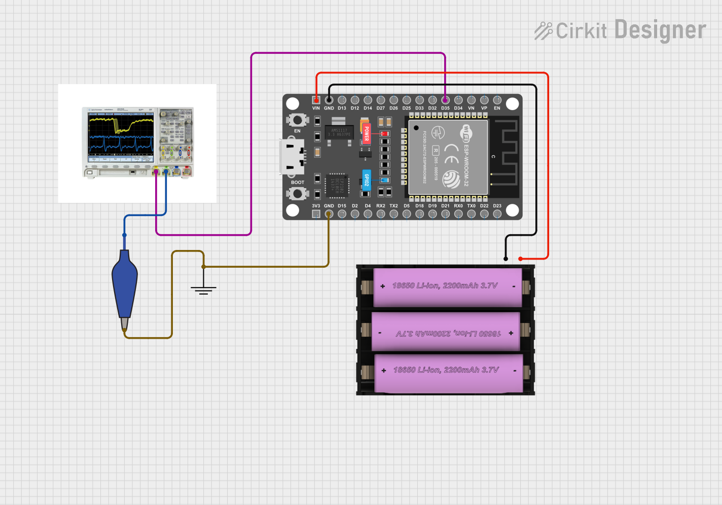
  1. Powering the Board:

    • Connect a 7-12V power supply to the VIN pin and GND, or use the micro USB port for power.
  2. Connecting to Wi-Fi:

    • Utilize the onboard Wi-Fi capabilities to connect to a network for IoT applications.
  3. Interfacing with Sensors:

    • Connect analog sensors to the ADC pins or digital sensors to the GPIO pins.
  4. Programming the Board:

    • Use the Arduino IDE or other development environments to write and upload code to the ESP32.

Important Considerations and Best Practices

  • Always ensure that the power supply is within the recommended voltage range to prevent damage.
  • When using Wi-Fi or Bluetooth, consider the power consumption and plan for power management in battery-operated projects.
  • Use proper decoupling capacitors close to the power pins to stabilize the power supply.
  • Avoid using pins 6-11 for GPIO as they are connected to the integrated SPI flash and using them may interfere with the operation of the flash memory.

Troubleshooting and FAQs

Common Issues

  • Board not recognized by the computer:
    • Ensure the micro USB cable is data-capable and the board drivers are installed.
  • Wi-Fi or Bluetooth not functioning:
    • Check the antenna connections and ensure the correct configuration in the code.

Solutions and Tips for Troubleshooting

  • If the board does not power on, check the power supply and cable connections.
  • For connectivity issues, verify the network credentials and signal strength.
  • Use the onboard LED as a simple debugging tool to indicate the status of the board.

FAQs

  • Q: Can I use the ESP32 DEVKIT V1 with a battery?

    • A: Yes, but ensure the battery voltage is within the recommended input range.
  • Q: How do I program the ESP32 DEVKIT V1?

    • A: You can program it using the Arduino IDE or other compatible development environments.
  • Q: What is the maximum current that the GPIO pins can handle?

    • A: Each GPIO pin can typically source or sink up to 12 mA.

Example Code for Arduino UNO

#include <WiFi.h>

// Replace with your network credentials
const char* ssid = "your_SSID";
const char* password = "your_PASSWORD";

void setup() {
  Serial.begin(115200);
  
  // Connect to Wi-Fi
  WiFi.begin(ssid, password);
  while (WiFi.status() != WL_CONNECTED) {
    delay(1000);
    Serial.println("Connecting to WiFi...");
  }
  Serial.println("Connected to WiFi");
}

void loop() {
  // Your code here
}

Note: This example demonstrates how to connect the ESP32 to a Wi-Fi network. Replace your_SSID and your_PASSWORD with your actual Wi-Fi credentials.

Remember to consult the ESP32 datasheet and technical reference manual for more detailed information on the microcontroller's capabilities and the development board's design.