How to Use Smart Relay Zelio SR3B261BD: Examples, Pinouts, and Specs
Introduction
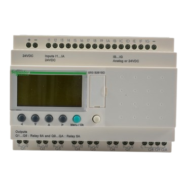
The Smart Relay Zelio SR3B261BD by Schneider Electric is a versatile programmable relay designed for automation applications. It features multiple input/output configurations, built-in communication capabilities, and user-friendly programming options. This relay is ideal for controlling electrical devices in industrial, commercial, and residential settings. Its compact design and robust functionality make it a popular choice for applications requiring efficient and reliable automation.
Explore Projects Built with Smart Relay Zelio SR3B261BD


Explore Projects Built with Smart Relay Zelio SR3B261BD
Common Applications and Use Cases
- Industrial machinery control
- Building automation systems
- Lighting control
- HVAC (Heating, Ventilation, and Air Conditioning) systems
- Small-scale process automation
- Motor and pump control
Technical Specifications
Key Technical Details
| Parameter | Specification |
|---|---|
| Power Supply Voltage | 24 V DC |
| Number of Inputs | 16 |
| Number of Outputs | 10 (Relay outputs) |
| Output Type | Relay (NO/NC contacts) |
| Maximum Output Current | 8 A per relay |
| Communication Interface | Modbus RTU (RS485) |
| Programming Language | Ladder Logic, Function Block Diagram |
| Operating Temperature Range | -20°C to +55°C |
| Dimensions (H x W x D) | 90 x 124 x 59 mm |
| Mounting Type | DIN Rail or Panel Mount |
Pin Configuration and Descriptions
The Zelio SR3B261BD has a total of 26 terminals, including input, output, and power connections. Below is the pin configuration:
Input Terminals
| Pin Number | Description | Type |
|---|---|---|
| I1 - I16 | Digital Inputs (24 V DC) | Input |
Output Terminals
| Pin Number | Description | Type |
|---|---|---|
| Q1 - Q10 | Relay Outputs (NO/NC) | Output |
Power and Communication Terminals
| Pin Number | Description | Type |
|---|---|---|
| L+ / L- | Power Supply (24 V DC) | Power |
| A / B | RS485 Communication (Modbus) | Communication |
Usage Instructions
How to Use the Component in a Circuit
- Power Connection: Connect a 24 V DC power supply to the L+ and L- terminals. Ensure the power supply is stable and within the specified voltage range.
- Input Connections: Connect sensors, switches, or other input devices to the input terminals (I1 to I16). Ensure the input devices are compatible with 24 V DC logic.
- Output Connections: Connect the devices you want to control (e.g., motors, lights) to the output terminals (Q1 to Q10). Verify that the load does not exceed the maximum current rating of 8 A per relay.
- Programming: Use Schneider Electric's Zelio Soft software to program the relay. You can create control logic using Ladder Logic or Function Block Diagram (FBD).
- Communication: If required, connect the RS485 communication lines (A and B) to integrate the relay into a Modbus RTU network.
Important Considerations and Best Practices
- Always verify the power supply voltage and polarity before powering the relay.
- Use proper fuses or circuit breakers to protect the relay and connected devices.
- Avoid exceeding the maximum current rating of the relay outputs to prevent damage.
- Ensure proper grounding of the system to minimize electrical noise and interference.
- Use shielded cables for RS485 communication to improve signal integrity.
- Regularly inspect and maintain the relay to ensure reliable operation.
Example Code for Arduino UNO Integration
The Zelio SR3B261BD can communicate with an Arduino UNO via Modbus RTU. Below is an example code snippet to read input status and control outputs:
#include <ModbusMaster.h>

// Create ModbusMaster object
ModbusMaster node;

// Define RS485 communication pins
#define RE_PIN 2  // Receiver Enable
#define DE_PIN 3  // Driver Enable

void preTransmission() {
  digitalWrite(RE_PIN, HIGH); // Enable transmission
  digitalWrite(DE_PIN, HIGH);
}

void postTransmission() {
  digitalWrite(RE_PIN, LOW);  // Disable transmission
  digitalWrite(DE_PIN, LOW);
}

void setup() {
  // Initialize serial communication
  Serial.begin(9600);

  // Initialize RS485 control pins
  pinMode(RE_PIN, OUTPUT);
  pinMode(DE_PIN, OUTPUT);
  digitalWrite(RE_PIN, LOW);
  digitalWrite(DE_PIN, LOW);

  // Initialize Modbus communication
  node.begin(1, Serial); // Slave ID = 1
  node.preTransmission(preTransmission);
  node.postTransmission(postTransmission);
}

void loop() {
  uint8_t result;
  uint16_t data;

  // Read input status (e.g., I1)
  result = node.readDiscreteInputs(0x0000, 16); // Read 16 inputs starting at 0x0000
  if (result == node.ku8MBSuccess) {
    data = node.getResponseBuffer(0);
    Serial.print("Input Status: ");
    Serial.println(data, BIN); // Print input status in binary
  }

  // Write to output (e.g., Q1)
  result = node.writeSingleCoil(0x0000, 1); // Set Q1 to ON
  if (result == node.ku8MBSuccess) {
    Serial.println("Output Q1 turned ON");
  }

  delay(1000); // Wait for 1 second
}
Notes:
- Use an RS485-to-TTL converter to connect the Arduino UNO to the Zelio relay.
- Adjust the slave ID and register addresses based on your specific configuration.
Troubleshooting and FAQs
Common Issues and Solutions
Relay Does Not Power On
- Verify the power supply voltage and polarity.
- Check for loose or damaged connections.
Inputs Not Detected
- Ensure the input devices are functioning correctly.
- Verify that the input voltage is within the specified range (24 V DC).
Outputs Not Activating
- Check the load connected to the output terminals.
- Ensure the load does not exceed the maximum current rating of 8 A.
- Verify the control logic in the program.
Communication Failure
- Check the RS485 wiring and ensure proper termination.
- Verify the Modbus slave ID and baud rate settings.
- Use shielded cables to reduce electrical noise.
FAQs
Q: Can the Zelio SR3B261BD be used with AC loads?
A: Yes, the relay outputs can control AC loads, but ensure the load current and voltage are within the relay's specifications.
Q: What software is required for programming?
A: Schneider Electric's Zelio Soft software is used for programming the relay.
Q: Can the relay be mounted on a DIN rail?
A: Yes, the Zelio SR3B261BD supports both DIN rail and panel mounting.
Q: Is the relay compatible with other PLCs?
A: Yes, the relay can communicate with other PLCs via Modbus RTU.
Q: How do I reset the relay to factory settings?
A: Refer to the Zelio Soft software manual for instructions on performing a factory reset.