
How to Use 9 Degrees of Freedom - Sensor Stick: Examples, Pinouts, and Specs

 Design with 9 Degrees of Freedom - Sensor Stick in Cirkit Designer
Introduction
The 9 Degrees of Freedom - Sensor Stick by SparkFun is a compact and versatile sensor module that integrates an accelerometer, gyroscope, and magnetometer. This combination allows the module to measure orientation, acceleration, angular velocity, and magnetic field strength in three-dimensional space. It is widely used in applications such as robotics, motion tracking, drone stabilization, and wearable devices.
This sensor stick is ideal for projects requiring precise motion and orientation data, offering a small form factor and compatibility with microcontrollers like Arduino.
Explore Projects Built with 9 Degrees of Freedom - Sensor Stick
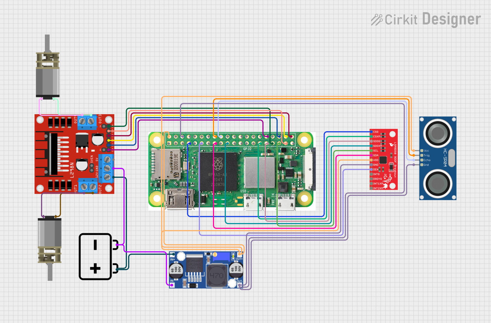 Open Project in Cirkit Designer
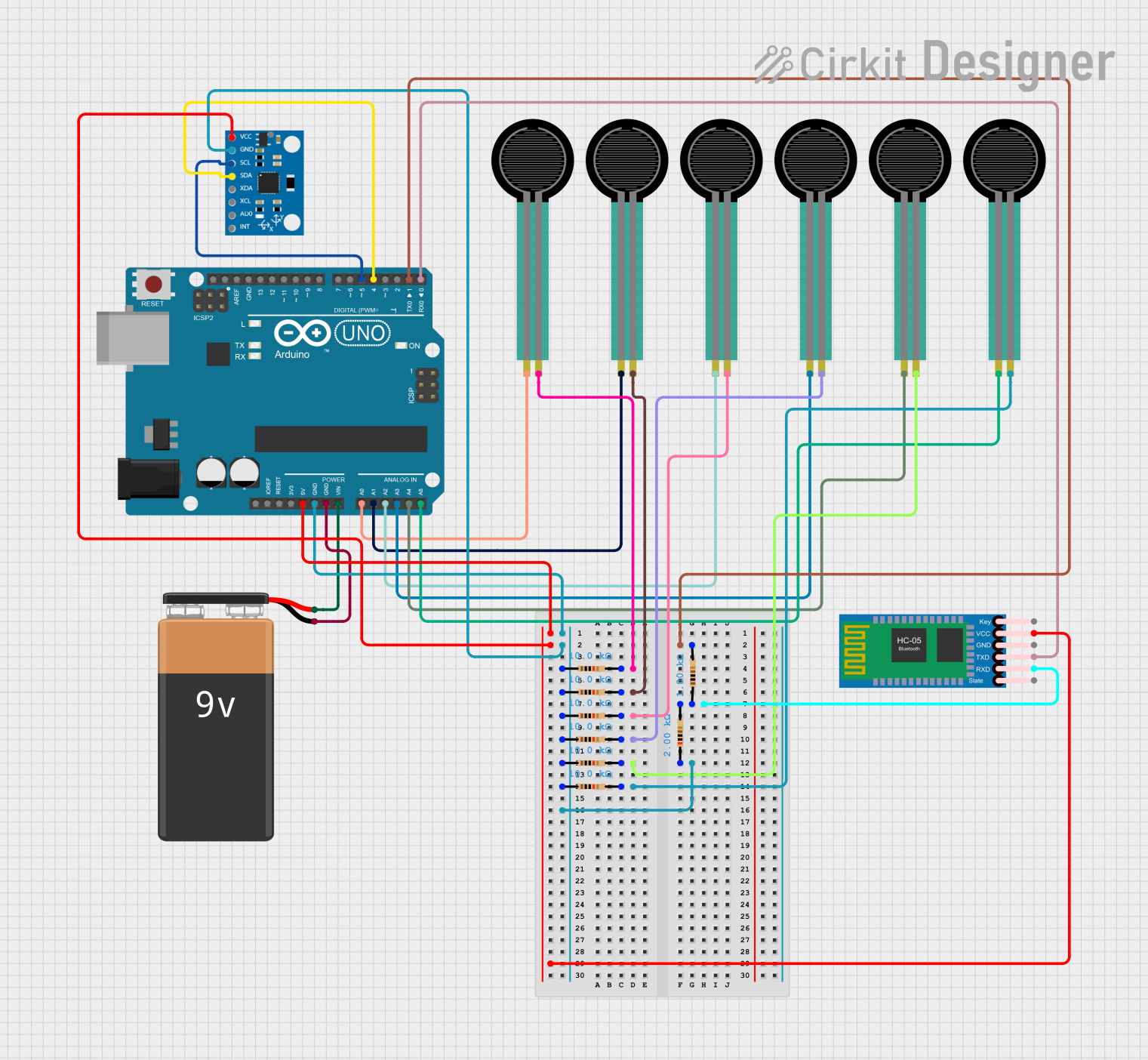 Open Project in Cirkit Designer
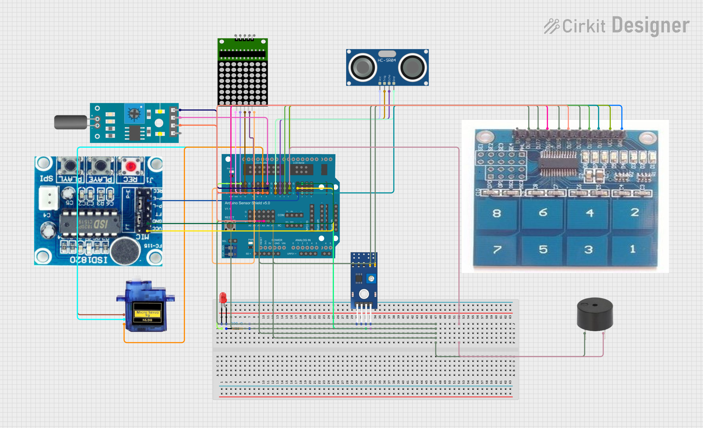 Open Project in Cirkit Designer
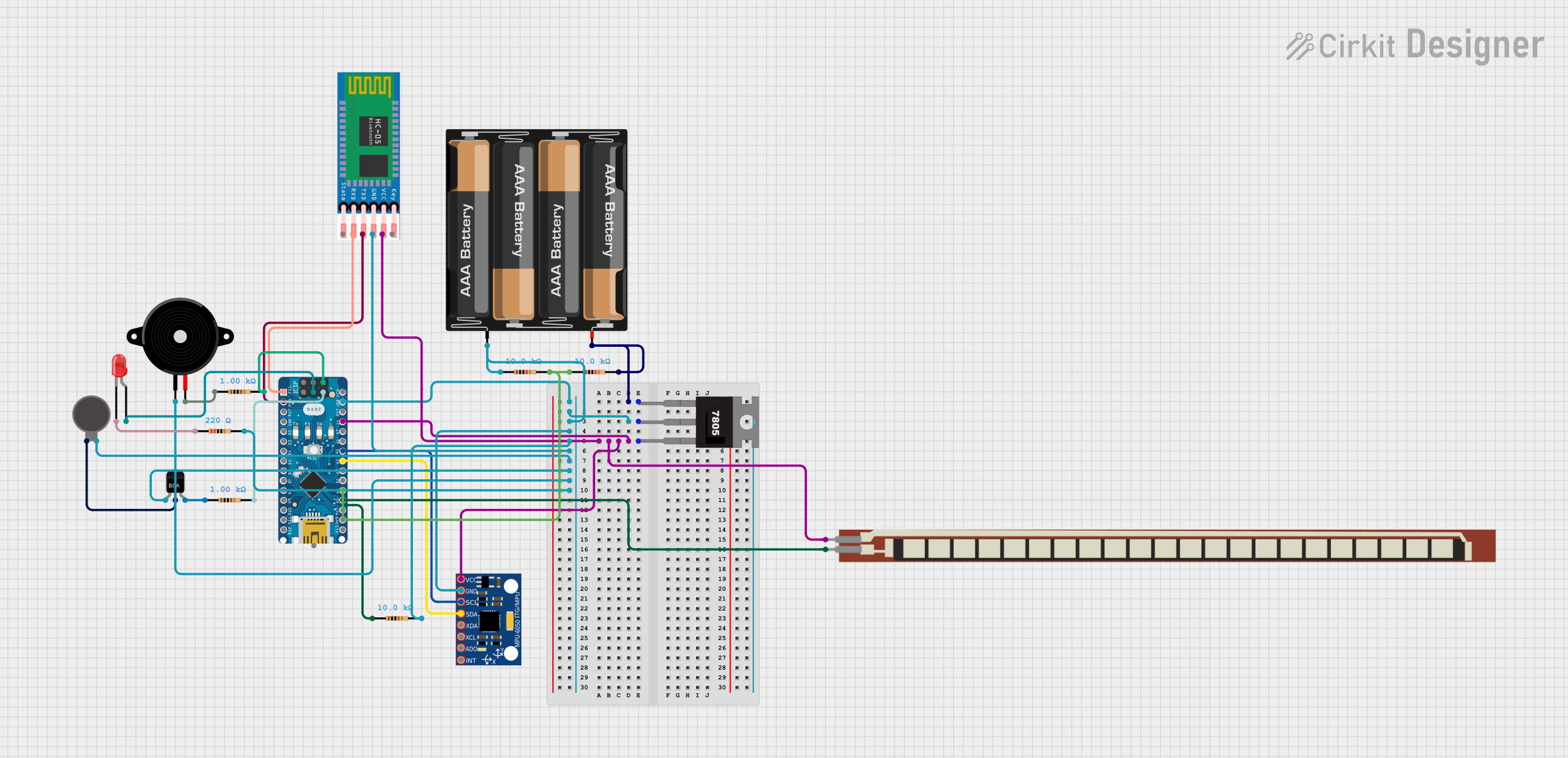 Open Project in Cirkit Designer
Explore Projects Built with 9 Degrees of Freedom - Sensor Stick
Open Project in Cirkit DesignerOpen Project in Cirkit DesignerOpen Project in Cirkit DesignerOpen Project in Cirkit DesignerTechnical Specifications
The following table outlines the key technical details of the 9 Degrees of Freedom - Sensor Stick:
| Specification | Details |
|---|---|
| Manufacturer | SparkFun |
| Sensor Components | Accelerometer (ADXL345), Gyroscope (ITG-3200), Magnetometer (HMC5883L) |
| Communication Protocols | I2C, SPI |
| Operating Voltage | 3.3V (logic level) |
| Input Voltage Range | 3.3V to 6V |
| Current Consumption | ~10mA (varies depending on usage) |
| Dimensions | 4.1 x 1.6 cm |
| Operating Temperature | -40°C to +85°C |
Pin Configuration and Descriptions
The sensor stick has the following pin layout:
| Pin | Name | Description |
|---|---|---|
| 1 | GND | Ground connection |
| 2 | VCC | Power supply input (3.3V to 6V) |
| 3 | SDA | I2C data line |
| 4 | SCL | I2C clock line |
| 5 | INT | Interrupt pin (used for motion detection or data-ready signals) |
| 6 | CS | Chip Select (used for SPI communication) |
| 7 | SDO | Serial Data Out (used for SPI communication) |
| 8 | SDI | Serial Data In (used for SPI communication) |
Usage Instructions
How to Use the Sensor Stick in a Circuit
- Powering the Sensor Stick: Connect the
VCCpin to a 3.3V or 5V power source and theGNDpin to ground. - Communication Setup:
- For I2C communication, connect the
SDAandSCLpins to the corresponding I2C pins on your microcontroller. - For SPI communication, connect the
CS,SDO, andSDIpins to the appropriate SPI pins on your microcontroller.
- For I2C communication, connect the
- Interrupt Pin: Optionally, connect the
INTpin to a digital input pin on your microcontroller to handle interrupts.
Important Considerations and Best Practices
- Voltage Levels: Ensure that the logic level of your microcontroller matches the sensor stick's 3.3V logic level. Use a level shifter if necessary.
- Pull-Up Resistors: The I2C lines (
SDAandSCL) require pull-up resistors. Many microcontroller boards, such as the Arduino UNO, already include these resistors. - Calibration: For accurate readings, calibrate the accelerometer, gyroscope, and magnetometer before use. This can be done using software libraries.
- Mounting: Secure the sensor stick firmly to avoid vibrations or movement that could affect readings.
Example Code for Arduino UNO
Below is an example of how to use the sensor stick with an Arduino UNO via I2C:
#include <Wire.h>
#include <Adafruit_Sensor.h>
#include <Adafruit_ADXL345_U.h>
#include <Adafruit_HMC5883_U.h>
#include <Adafruit_ITG3200.h>

// Create sensor objects
Adafruit_ADXL345_Unified accel = Adafruit_ADXL345_Unified(12345);
Adafruit_HMC5883_Unified mag = Adafruit_HMC5883_Unified(12345);
Adafruit_ITG3200 gyro;

void setup() {
  Serial.begin(9600);
  Wire.begin();

  // Initialize accelerometer
  if (!accel.begin()) {
    Serial.println("Failed to initialize ADXL345 accelerometer!");
    while (1);
  }
  Serial.println("ADXL345 accelerometer initialized.");

  // Initialize magnetometer
  if (!mag.begin()) {
    Serial.println("Failed to initialize HMC5883 magnetometer!");
    while (1);
  }
  Serial.println("HMC5883 magnetometer initialized.");

  // Initialize gyroscope
  if (!gyro.begin()) {
    Serial.println("Failed to initialize ITG-3200 gyroscope!");
    while (1);
  }
  Serial.println("ITG-3200 gyroscope initialized.");
}

void loop() {
  // Read accelerometer data
  sensors_event_t accelEvent;
  accel.getEvent(&accelEvent);
  Serial.print("Accel X: "); Serial.print(accelEvent.acceleration.x);
  Serial.print(" Y: "); Serial.print(accelEvent.acceleration.y);
  Serial.print(" Z: "); Serial.println(accelEvent.acceleration.z);

  // Read magnetometer data
  sensors_event_t magEvent;
  mag.getEvent(&magEvent);
  Serial.print("Mag X: "); Serial.print(magEvent.magnetic.x);
  Serial.print(" Y: "); Serial.print(magEvent.magnetic.y);
  Serial.print(" Z: "); Serial.println(magEvent.magnetic.z);

  // Read gyroscope data
  float gx, gy, gz;
  gyro.getRotation(&gx, &gy, &gz);
  Serial.print("Gyro X: "); Serial.print(gx);
  Serial.print(" Y: "); Serial.print(gy);
  Serial.print(" Z: "); Serial.println(gz);

  delay(500); // Delay for readability
}
Troubleshooting and FAQs
Common Issues
No Data Output:
- Ensure the sensor stick is powered correctly and the connections are secure.
- Verify that the I2C or SPI communication lines are properly connected.
- Check the I2C address of the sensors and ensure it matches the library settings.
Inaccurate Readings:
- Perform a calibration for all three sensors (accelerometer, gyroscope, and magnetometer).
- Minimize external magnetic interference for the magnetometer.
Communication Errors:
- Ensure pull-up resistors are present on the I2C lines.
- Check for conflicting I2C addresses if multiple devices are connected.
Tips for Troubleshooting
- Use a multimeter to verify power and ground connections.
- Test each sensor individually to isolate issues.
- Refer to the SparkFun product page for additional resources and example code.
By following this documentation, you can effectively integrate the 9 Degrees of Freedom - Sensor Stick into your projects and achieve accurate motion and orientation tracking.