How to Use ESP 32 Wroom Dev Kit: Examples, Pinouts, and Specs
Introduction
The ESP32-WROOM Dev Kit is a powerful, versatile development board that integrates the ESP32-WROOM-32 module. This board is widely used for Internet of Things (IoT) applications due to its built-in Wi-Fi and Bluetooth capabilities. It is suitable for a variety of uses, including smart home devices, wireless sensors, and other connected projects.
Explore Projects Built with ESP 32 Wroom Dev Kit


Explore Projects Built with ESP 32 Wroom Dev Kit
Technical Specifications
Key Technical Details
- Microcontroller: ESP32-D0WDQ6
- Operating Voltage: 3.3V
- Input Voltage: 5V via micro USB or Vin pin
- Digital I/O Pins: 22
- Analog Input Pins: 6 (VP, VN, 32, 33, 34, 35)
- Flash Memory: 4MB
- SRAM: 520 KB
- Clock Speed: Up to 240MHz
- Wi-Fi: 802.11 b/g/n
- Bluetooth: v4.2 BR/EDR and BLE
- Operating Temperature: -40°C to +125°C
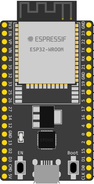
Pin Configuration and Descriptions
| Pin Number | Function | Description |
|---|---|---|
| 1 | 3V3 | 3.3V power supply |
| 2 | GND | Ground |
| 3 | EN | Reset pin (active low) |
| 4 | VP | ADC channel 7 / Sensor VP |
| 5 | VN | ADC channel 6 / Sensor VN |
| 6-11 | IO34 - IO39 | General purpose IO / ADC channels |
| 12-14 | IO12 - IO14 | General purpose IO with PWM capability |
| 15 | IO27 | General purpose IO with PWM capability |
| 16-17 | IO25 - IO26 | DAC channels |
| 18-23 | IO32 - IO33 | General purpose IO with PWM capability |
| 24-29 | IO18 - IO23 | General purpose IO / SPI interface |
| 30 | GND | Ground |
| 31 | 5V | 5V power supply (via USB or Vin pin) |
| 32-37 | TX0, RX0, IO5, | Serial communication and general purpose IO |
| IO17, IO16, IO4 | ||
| 38-43 | IO0, IO2, IO15, | General purpose IO with boot mode selection |
| IO13, IO12, IO14 | and PWM capability |
Usage Instructions
Integrating with a Circuit
To use the ESP32-WROOM Dev Kit in a circuit:
- Powering the Board: Connect a 5V power supply to the micro USB port or Vin pin.
- Connecting I/O Pins: Utilize the GPIO pins for interfacing with sensors, actuators, and other peripherals.
- Programming the Board: Use the micro USB port to connect the board to a computer for programming.
Best Practices
- Power Supply: Ensure that the power supply is stable and within the specified voltage range to prevent damage.
- I/O Pin Protection: Use current-limiting resistors to protect the GPIO pins from overcurrent conditions.
- Antenna Clearance: Keep the area around the antenna free from metal objects to ensure proper Wi-Fi and Bluetooth signal propagation.
- ESD Precautions: Handle the board with proper electrostatic discharge (ESD) precautions to avoid damaging the sensitive electronics.
Troubleshooting and FAQs
Common Issues
- Board Not Powering Up: Check the power supply and cable connections. Ensure the EN pin is not being held low.
- Failure to Connect to Wi-Fi: Verify the Wi-Fi credentials and signal strength. Ensure the antenna area is clear of obstructions.
- Programming Errors: Ensure the correct board settings are selected in the IDE and the drivers are installed.
FAQs
Q: Can I use the ESP32-WROOM Dev Kit with Arduino IDE?
- A: Yes, the board is compatible with the Arduino IDE. You will need to install the ESP32 board package.
Q: What is the maximum current draw for the I/O pins?
- A: The maximum current per I/O pin is 12 mA.
Q: How do I reset the board?
- A: Briefly connect the EN pin to GND or press the reset button if available.
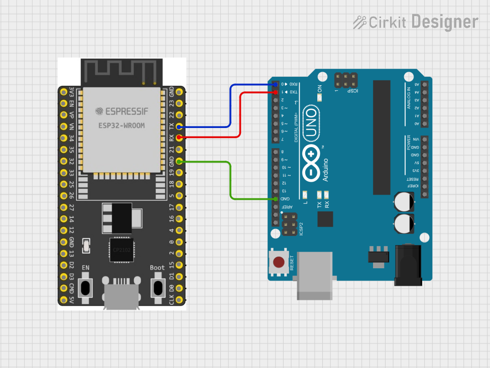
Example Code for Arduino UNO
Below is a simple example of how to blink an LED connected to the ESP32-WROOM Dev Kit using the Arduino IDE.
// Define the LED pin
const int LED_PIN = 2; // Use GPIO2 for the LED

// Setup function runs once at the start
void setup() {
  // Initialize the LED pin as an output
  pinMode(LED_PIN, OUTPUT);
}

// Loop function runs repeatedly
void loop() {
  digitalWrite(LED_PIN, HIGH); // Turn the LED on
  delay(1000);                // Wait for a second
  digitalWrite(LED_PIN, LOW);  // Turn the LED off
  delay(1000);                // Wait for a second
}
Remember to select the correct board and port in the Arduino IDE before uploading the code to the ESP32-WROOM Dev Kit.