How to Use 2.8 240 324 ILI9341: Examples, Pinouts, and Specs
Introduction
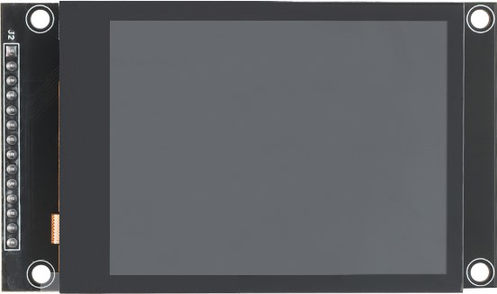
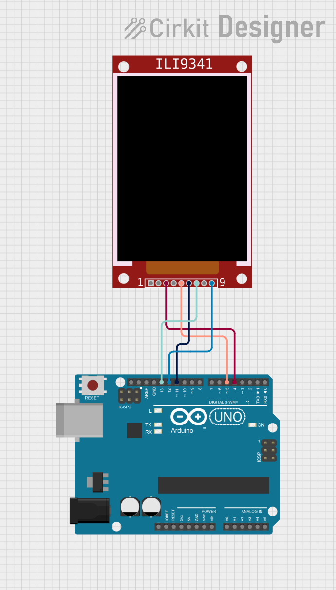
The 2.8 240 324 ILI9341 is a 2.8-inch TFT LCD display module with a resolution of 240x320 pixels. It features the ILI9341 driver, which enables seamless interfacing with microcontrollers such as Arduino, ESP32, and STM32. This display module supports 65K colors and offers a touch panel option, making it ideal for creating interactive graphical user interfaces.
Explore Projects Built with 2.8 240 324 ILI9341
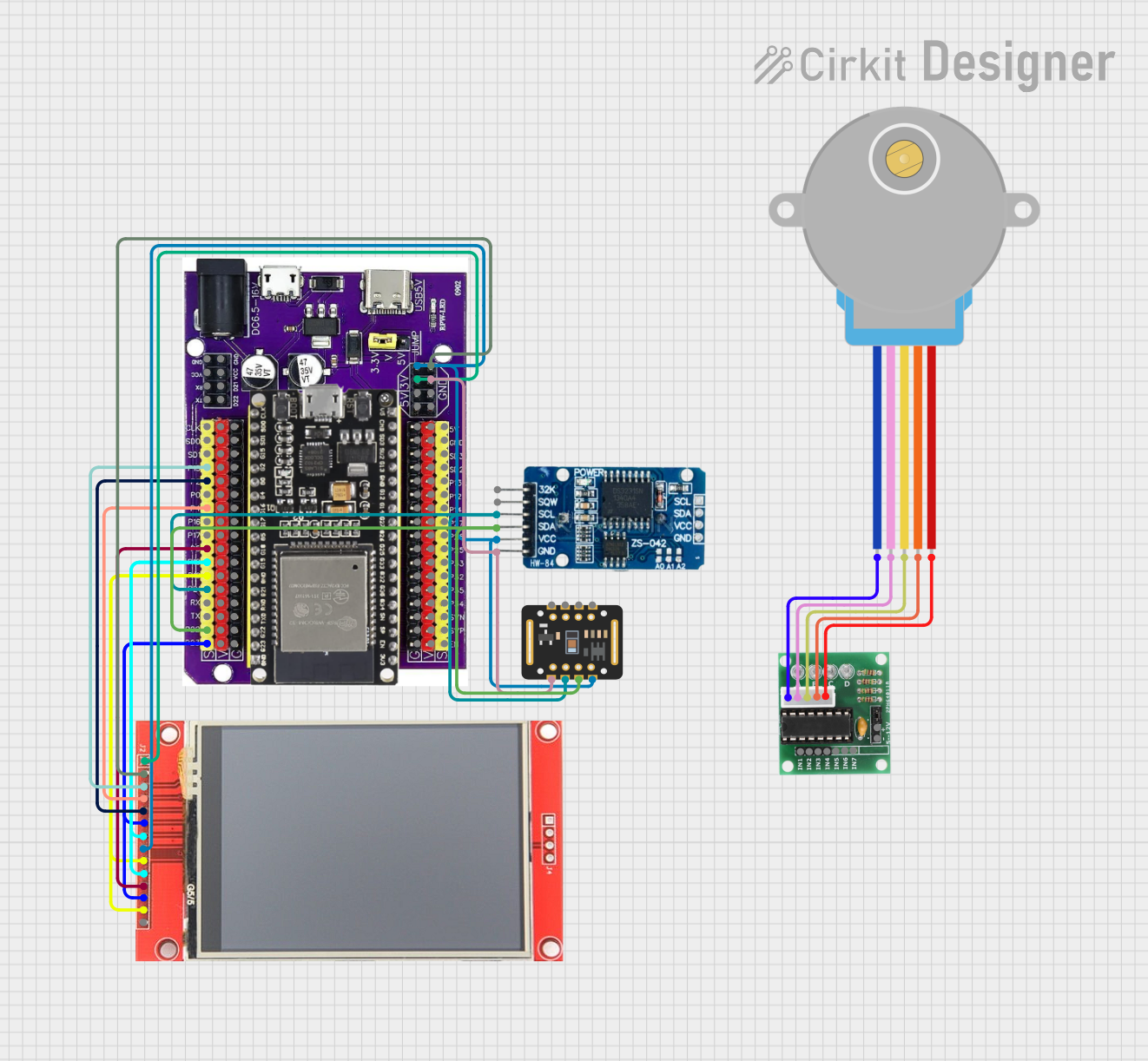
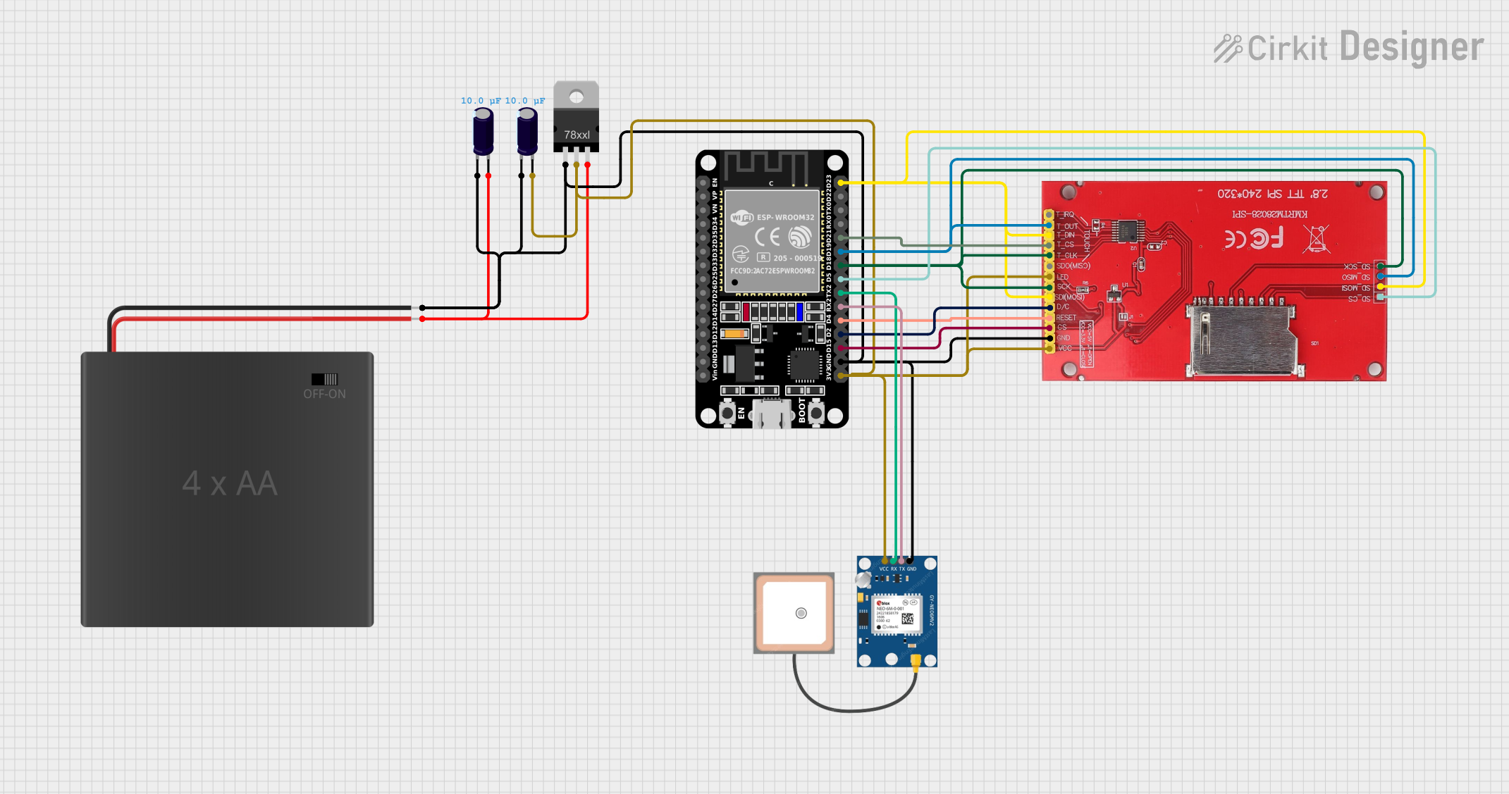
Explore Projects Built with 2.8 240 324 ILI9341
Common Applications and Use Cases
- Graphical user interfaces for embedded systems
- Portable devices with visual output
- DIY projects requiring a color display
- Industrial control panels
- Educational and prototyping purposes
Technical Specifications
Below are the key technical details of the 2.8 240 324 ILI9341 display module:
| Parameter | Specification |
|---|---|
| Display Type | TFT LCD |
| Screen Size | 2.8 inches |
| Resolution | 240x320 pixels |
| Driver IC | ILI9341 |
| Color Depth | 65K colors (16-bit RGB) |
| Interface | SPI (Serial Peripheral Interface) |
| Operating Voltage | 3.3V (logic level) |
| Backlight Voltage | 3.3V to 5V |
| Current Consumption | ~50mA (varies with backlight usage) |
| Touch Panel (Optional) | Resistive |
Pin Configuration and Descriptions
The module typically has 8 to 10 pins for interfacing. Below is the pinout:
| Pin | Name | Description |
|---|---|---|
| 1 | VCC | Power supply input (3.3V or 5V, depending on the module version). |
| 2 | GND | Ground connection. |
| 3 | CS | Chip Select pin for SPI communication. |
| 4 | RESET | Reset pin to initialize the display. |
| 5 | DC | Data/Command pin to distinguish between data and command signals. |
| 6 | SDI/MOSI | Serial Data Input / Master Out Slave In for SPI communication. |
| 7 | SCK | Serial Clock for SPI communication. |
| 8 | LED | Backlight control pin (connect to 3.3V or 5V for constant backlight). |
| 9 | SDO/MISO | Serial Data Output / Master In Slave Out (optional, used for SPI read). |
| 10 | T_IRQ | Touch interrupt pin (used only if the touch panel is present). |
Usage Instructions
How to Use the Component in a Circuit
- Power Supply: Connect the
VCCpin to a 3.3V or 5V power source (depending on the module version) and theGNDpin to ground. - SPI Communication: Connect the
CS,RESET,DC,SDI/MOSI, andSCKpins to the corresponding SPI pins on your microcontroller. - Backlight: Connect the
LEDpin to 3.3V or 5V for constant backlight. Optionally, use a PWM pin on your microcontroller to control brightness. - Touch Panel (Optional): If the module includes a touch panel, connect the
T_IRQpin to a GPIO pin on your microcontroller for touch detection.
Important Considerations and Best Practices
- Voltage Levels: Ensure that the logic voltage levels of your microcontroller match the display module (3.3V). Use level shifters if necessary.
- SPI Speed: Configure the SPI clock speed appropriately. A typical value is 4 MHz, but the ILI9341 can support higher speeds depending on your setup.
- Initialization: Always initialize the display using the correct sequence of commands as specified in the ILI9341 datasheet.
- Library Support: Use well-supported libraries like Adafruit_GFX and Adafruit_ILI9341 for Arduino to simplify development.
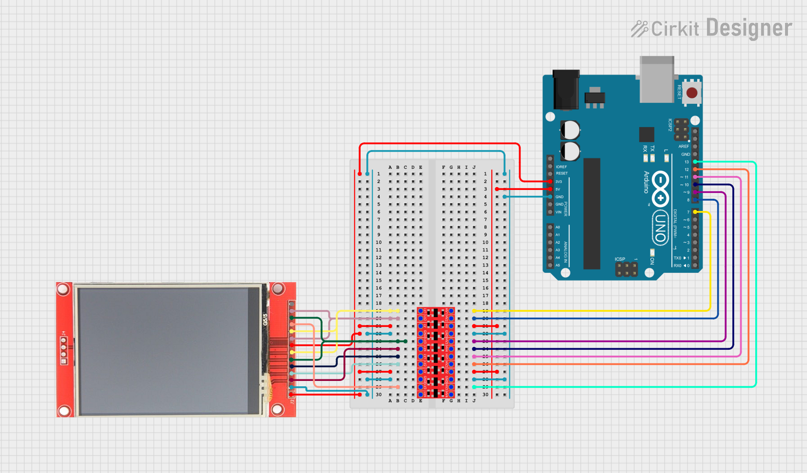
Example Code for Arduino UNO
Below is an example of how to interface the 2.8 240 324 ILI9341 with an Arduino UNO using the Adafruit_ILI9341 library:
#include <Adafruit_GFX.h>      // Core graphics library
#include <Adafruit_ILI9341.h>  // ILI9341 driver library

// Define pin connections
#define TFT_CS   10  // Chip Select
#define TFT_DC    9  // Data/Command
#define TFT_RST   8  // Reset (optional)

// Create an instance of the display
Adafruit_ILI9341 tft = Adafruit_ILI9341(TFT_CS, TFT_DC, TFT_RST);

void setup() {
  // Initialize serial communication for debugging
  Serial.begin(9600);
  Serial.println("Initializing display...");

  // Initialize the display
  tft.begin();

  // Set rotation (0-3)
  tft.setRotation(1);

  // Fill the screen with a color
  tft.fillScreen(ILI9341_BLUE);

  // Draw a rectangle
  tft.fillRect(50, 50, 100, 100, ILI9341_RED);

  // Display text
  tft.setTextColor(ILI9341_WHITE);
  tft.setTextSize(2);
  tft.setCursor(10, 10);
  tft.println("Hello, ILI9341!");
}

void loop() {
  // Nothing to do here
}
Troubleshooting and FAQs
Common Issues Users Might Face
Blank Screen:
- Ensure the
VCCandGNDpins are properly connected. - Verify that the SPI connections are correct and secure.
- Check the initialization sequence in your code.
- Ensure the
Flickering or Noisy Display:
- Reduce the SPI clock speed.
- Ensure proper grounding and minimize noise in the power supply.
Touch Panel Not Responding:
- Confirm that the touch panel pins (
T_IRQ, etc.) are connected correctly. - Use a compatible touch library if required.
- Confirm that the touch panel pins (
Incorrect Colors or Artifacts:
- Verify that the color format (16-bit RGB) is correctly configured in your code.
- Check for loose connections or damaged wires.
Solutions and Tips for Troubleshooting
- Use a multimeter to verify voltage levels at the module pins.
- Test the module with a known working example code to rule out software issues.
- Refer to the ILI9341 datasheet for detailed timing and initialization requirements.
By following this documentation, you can effectively integrate the 2.8 240 324 ILI9341 display module into your projects and troubleshoot common issues with ease.