
How to Use 3 phase supply: Examples, Pinouts, and Specs

 Design with 3 phase supply in Cirkit Designer
Introduction
A 3 phase supply is an electrical power system that uses three alternating currents, each phase offset by 120 degrees. This configuration provides a more efficient and stable power distribution compared to single-phase systems. It is widely used in industrial and commercial applications due to its ability to deliver consistent power to heavy machinery and equipment.
Explore Projects Built with 3 phase supply
 Open Project in Cirkit Designer
 Open Project in Cirkit Designer
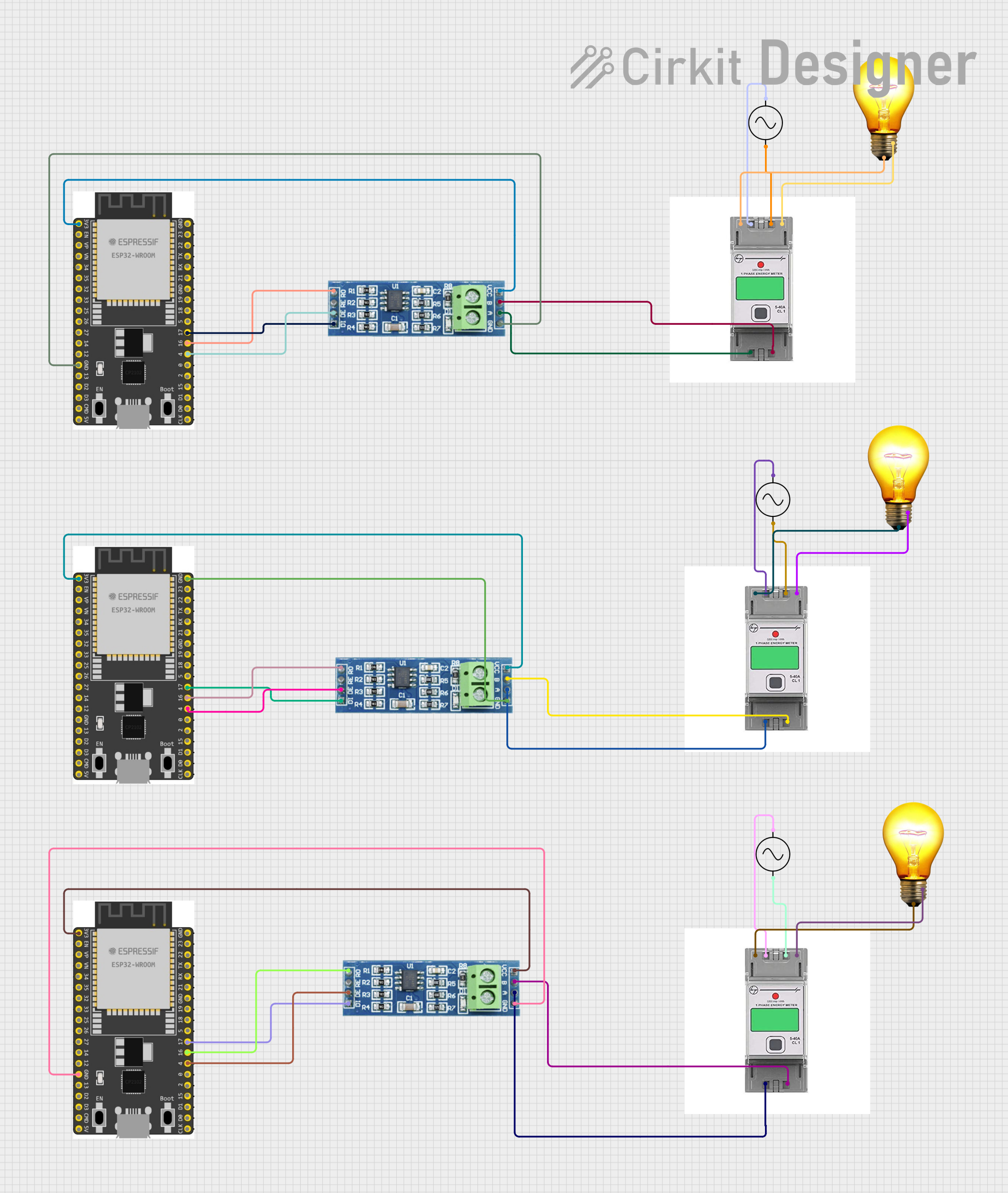 Open Project in Cirkit Designer
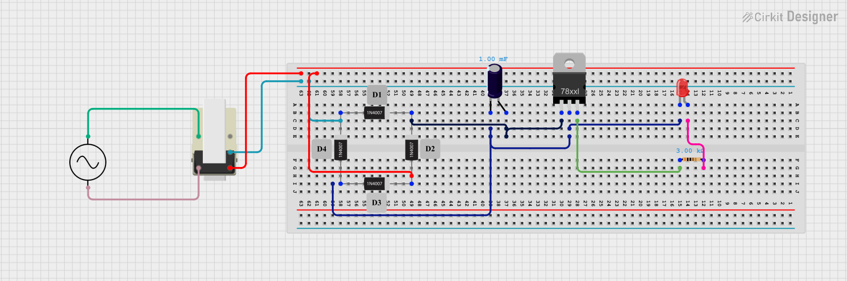 Open Project in Cirkit Designer
Explore Projects Built with 3 phase supply
Open Project in Cirkit DesignerOpen Project in Cirkit DesignerOpen Project in Cirkit DesignerOpen Project in Cirkit DesignerCommon Applications and Use Cases
- Powering industrial motors and heavy machinery
- Commercial HVAC systems
- Data centers and server farms
- High-power lighting systems
- Renewable energy systems (e.g., wind turbines, solar inverters)
Technical Specifications
Below are the key technical details of a standard 3 phase supply system:
| Parameter | Description |
|---|---|
| Voltage Levels | Commonly 208V, 400V, or 480V (varies by region and application) |
| Frequency | 50 Hz or 60 Hz (depending on the country) |
| Phase Angle | 120° phase shift between each phase |
| Power Rating | Typically ranges from a few kW to several MW |
| Connection Types | Star (Wye) or Delta configurations |
| Neutral Line | Present in Star configuration; absent in Delta configuration |
| Current Rating | Depends on the load and system design |
Pin Configuration and Descriptions
For a 3 phase supply, the connections are typically as follows:
Star (Wye) Configuration
| Pin Name | Description |
|---|---|
| L1 | Phase 1 (Line 1) |
| L2 | Phase 2 (Line 2) |
| L3 | Phase 3 (Line 3) |
| N | Neutral (optional, used for single-phase loads or unbalanced systems) |
| PE | Protective Earth (ground connection for safety) |
Delta Configuration
| Pin Name | Description |
|---|---|
| L1 | Phase 1 (Line 1) |
| L2 | Phase 2 (Line 2) |
| L3 | Phase 3 (Line 3) |
| PE | Protective Earth (ground connection for safety) |
Usage Instructions
How to Use the Component in a Circuit
- Identify the Configuration: Determine whether the system uses a Star (Wye) or Delta configuration.
- Connect the Phases:
- For Star configuration, connect L1, L2, and L3 to the respective phase terminals of the load.
- For Delta configuration, connect L1, L2, and L3 in a closed loop to the load.
- Neutral Connection: If using a Star configuration, connect the Neutral (N) terminal to the load if required.
- Protective Earth: Always connect the PE terminal to the ground for safety.
- Verify Voltage and Frequency: Ensure the voltage and frequency match the load requirements.
- Turn On the Supply: After verifying all connections, power on the 3 phase supply.
Important Considerations and Best Practices
- Load Balancing: Ensure the load is evenly distributed across all three phases to prevent overloading.
- Safety Precautions: Always use proper insulation and grounding to avoid electrical hazards.
- Circuit Protection: Use circuit breakers or fuses to protect the system from overcurrent or short circuits.
- Voltage Compatibility: Verify that the connected equipment is rated for the supply voltage and frequency.
- Monitoring: Use a 3 phase power meter to monitor voltage, current, and power consumption.
Example: Connecting a 3 Phase Motor to an Arduino UNO
While an Arduino UNO cannot directly handle a 3 phase supply, it can control a 3 phase motor via a motor driver. Below is an example code snippet for controlling a 3 phase motor using an Arduino UNO and a motor driver:
// Example: Controlling a 3 phase motor with Arduino UNO
// Ensure the motor driver is compatible with the 3 phase motor and supply

const int pwmPin1 = 9; // PWM signal for Phase 1
const int pwmPin2 = 10; // PWM signal for Phase 2
const int pwmPin3 = 11; // PWM signal for Phase 3

void setup() {
  pinMode(pwmPin1, OUTPUT); // Set Phase 1 pin as output
  pinMode(pwmPin2, OUTPUT); // Set Phase 2 pin as output
  pinMode(pwmPin3, OUTPUT); // Set Phase 3 pin as output
}

void loop() {
  // Generate PWM signals for the 3 phases
  analogWrite(pwmPin1, 128); // 50% duty cycle for Phase 1
  analogWrite(pwmPin2, 192); // 75% duty cycle for Phase 2
  analogWrite(pwmPin3, 64);  // 25% duty cycle for Phase 3

  delay(1000); // Wait for 1 second
}
Note: This is a simplified example. In real-world applications, you would use a dedicated motor driver or inverter to handle the 3 phase supply and motor control.
Troubleshooting and FAQs
Common Issues Users Might Face
- Unbalanced Load: One phase carries more current than the others.
- Solution: Redistribute the load evenly across all three phases.
- Voltage Drop: Voltage at the load is lower than expected.
- Solution: Check for loose connections or undersized cables.
- Overheating Equipment: Motors or other equipment overheating.
- Solution: Verify that the equipment is rated for the supply voltage and frequency.
- Tripped Circuit Breakers: Breakers trip frequently.
- Solution: Check for short circuits, overcurrent, or faulty equipment.
FAQs
Q: Can I use a 3 phase supply for single-phase equipment?
A: Yes, in a Star configuration, you can use one phase and the Neutral line to power single-phase equipment.
Q: What happens if one phase fails?
A: This is called a "single phasing" condition. It can cause equipment to malfunction or overheat. Install phase failure relays to protect against this.
Q: How do I measure the power in a 3 phase system?
A: Use a 3 phase power meter to measure voltage, current, and power for each phase.
Q: Can I convert a 3 phase supply to single-phase?
A: Yes, using a phase converter or by connecting to one phase and Neutral in a Star configuration. However, this reduces the available power.
Q: Is a Neutral line always required?
A: No, Neutral is only required for unbalanced loads or single-phase equipment in a Star configuration. Delta configurations do not use a Neutral line.