Cirkit Designer Logo
Cirkit Designer
Your all-in-one circuit design IDE
Home / 
Component Documentation

How to Use MT3608: Examples, Pinouts, and Specs

Image of MT3608
Cirkit Designer LogoDesign with MT3608 in Cirkit Designer

Introduction

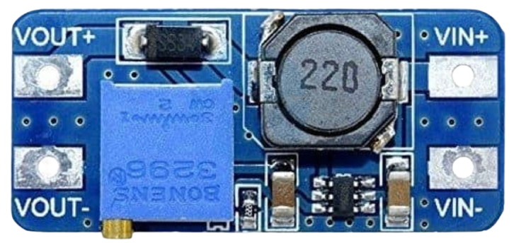
The MT3608 is a high-efficiency step-up (boost) DC-DC converter designed to increase input voltage to a higher output voltage. It is widely used in battery-powered devices where a higher voltage is required to power components such as LEDs, sensors, microcontrollers, and other electronic circuits. Its compact size, high efficiency, and adjustable output voltage make it a versatile choice for a variety of applications.

Explore Projects Built with MT3608

Use Cirkit Designer to design, explore, and prototype these projects online. Some projects support real-time simulation. Click "Open Project" to start designing instantly!
ESP32-Controlled Bluetooth Robotic Vehicle with MT3608 Boost Converters and L298N Motor Drivers
Image of Copy of Diagrama Elétrico - AutoBots (1): A project utilizing MT3608 in a practical application
This circuit is designed to control multiple DC motors and a servo motor using an ESP32 microcontroller, which is interfaced with Bluetooth for wireless control commands. The ESP32 outputs control signals to two L298N motor drivers, which in turn drive the DC motors. The MT3608 modules are used to step up the voltage from a 4 x AAA battery mount to power the motor drivers, while the servo motor is directly controlled by the ESP32.
Cirkit Designer LogoOpen Project in Cirkit Designer
Voltage Regulation System with MT3608 Boost and LM2596 Buck Converters
Image of solar system router ups: A project utilizing MT3608 in a practical application
This circuit consists of two MT3608 boost converters and an LM2596 step-down module, each connected to separate 12V power supplies. The MT3608 modules are configured to step up the voltage from their respective power supplies, while the LM2596 module steps down the voltage from a 12V battery. Diodes are used to ensure correct current flow direction, potentially for protection or isolation between different parts of the circuit.
Cirkit Designer LogoOpen Project in Cirkit Designer
ESP32-Powered Obstacle Avoidance Robot with IR and Ultrasonic Sensors
Image of projcememek: A project utilizing MT3608 in a practical application
This circuit features a 18650 Li-Ion battery connected to a TP4056 charging module, which in turn is connected to an MT3608 boost converter to step up the voltage. The output of the MT3608 powers an ESP32 microcontroller, a TCRT 5000 IR sensor, an HC-SR04 ultrasonic sensor, and an MG996R servo motor. The ESP32 is configured to control the servo motor via GPIO 27 and to receive input signals from the IR sensor and ultrasonic sensor through GPIO 14 and GPIO 13, respectively.
Cirkit Designer LogoOpen Project in Cirkit Designer
ESP32-Controlled Traffic Light and DC Motors with MT3608 Boost Converters
Image of Diagrama Elétrico - AutoBots: A project utilizing MT3608 in a practical application
This circuit is designed to control a traffic light and multiple DC motors using an ESP32 microcontroller. The ESP32's GPIO pins are connected to the traffic light to control the green, yellow, and red LEDs, and to the L298N motor drivers for controlling the speed and direction of the DC motors. The MT3608 modules are used to step up the voltage from the AAA batteries to power the motor drivers, and the MG996R servo is controlled by the ESP32 for additional actuation tasks.
Cirkit Designer LogoOpen Project in Cirkit Designer

Explore Projects Built with MT3608

Use Cirkit Designer to design, explore, and prototype these projects online. Some projects support real-time simulation. Click "Open Project" to start designing instantly!
Image of Copy of Diagrama Elétrico - AutoBots (1): A project utilizing MT3608 in a practical application
ESP32-Controlled Bluetooth Robotic Vehicle with MT3608 Boost Converters and L298N Motor Drivers
This circuit is designed to control multiple DC motors and a servo motor using an ESP32 microcontroller, which is interfaced with Bluetooth for wireless control commands. The ESP32 outputs control signals to two L298N motor drivers, which in turn drive the DC motors. The MT3608 modules are used to step up the voltage from a 4 x AAA battery mount to power the motor drivers, while the servo motor is directly controlled by the ESP32.
Cirkit Designer LogoOpen Project in Cirkit Designer
Image of solar system router ups: A project utilizing MT3608 in a practical application
Voltage Regulation System with MT3608 Boost and LM2596 Buck Converters
This circuit consists of two MT3608 boost converters and an LM2596 step-down module, each connected to separate 12V power supplies. The MT3608 modules are configured to step up the voltage from their respective power supplies, while the LM2596 module steps down the voltage from a 12V battery. Diodes are used to ensure correct current flow direction, potentially for protection or isolation between different parts of the circuit.
Cirkit Designer LogoOpen Project in Cirkit Designer
Image of projcememek: A project utilizing MT3608 in a practical application
ESP32-Powered Obstacle Avoidance Robot with IR and Ultrasonic Sensors
This circuit features a 18650 Li-Ion battery connected to a TP4056 charging module, which in turn is connected to an MT3608 boost converter to step up the voltage. The output of the MT3608 powers an ESP32 microcontroller, a TCRT 5000 IR sensor, an HC-SR04 ultrasonic sensor, and an MG996R servo motor. The ESP32 is configured to control the servo motor via GPIO 27 and to receive input signals from the IR sensor and ultrasonic sensor through GPIO 14 and GPIO 13, respectively.
Cirkit Designer LogoOpen Project in Cirkit Designer
Image of Diagrama Elétrico - AutoBots: A project utilizing MT3608 in a practical application
ESP32-Controlled Traffic Light and DC Motors with MT3608 Boost Converters
This circuit is designed to control a traffic light and multiple DC motors using an ESP32 microcontroller. The ESP32's GPIO pins are connected to the traffic light to control the green, yellow, and red LEDs, and to the L298N motor drivers for controlling the speed and direction of the DC motors. The MT3608 modules are used to step up the voltage from the AAA batteries to power the motor drivers, and the MG996R servo is controlled by the ESP32 for additional actuation tasks.
Cirkit Designer LogoOpen Project in Cirkit Designer

Common Applications

  • Powering LEDs and LED strips
  • Boosting voltage for microcontrollers and sensors
  • Portable battery-powered devices
  • DIY electronics projects
  • Solar-powered systems

Technical Specifications

The MT3608 is a highly efficient boost converter with the following key specifications:

Parameter Value
Input Voltage Range 2V to 24V
Output Voltage Range 2V to 28V (adjustable via potentiometer)
Maximum Output Current 2A (dependent on input voltage and load)
Efficiency Up to 93%
Switching Frequency 1.2 MHz
Operating Temperature -40°C to +85°C
Dimensions ~36mm x 17mm x 6mm

Pin Configuration and Descriptions

The MT3608 module typically has the following pins:

Pin Name Description
VIN Input voltage pin. Connect the positive terminal of the input power source here.
GND Ground pin. Connect to the negative terminal of the input power source.
VOUT Output voltage pin. Provides the boosted voltage.
EN (optional) Enable pin. Used to enable or disable the module (not always present).

Usage Instructions

How to Use the MT3608 in a Circuit

  1. Connect the Input Voltage:

    • Connect the positive terminal of your power source (e.g., battery) to the VIN pin.
    • Connect the negative terminal of your power source to the GND pin.
  2. Adjust the Output Voltage:

    • Use the onboard potentiometer to adjust the output voltage.
    • Turn the potentiometer clockwise to increase the output voltage and counterclockwise to decrease it.
    • Use a multimeter to measure the output voltage at the VOUT pin while adjusting.
  3. Connect the Load:

    • Connect the positive terminal of your load (e.g., LED, sensor) to the VOUT pin.
    • Connect the negative terminal of your load to the GND pin.
  4. Power On:

    • Once all connections are secure, power on the input source. The MT3608 will boost the input voltage to the desired output voltage.

Important Considerations and Best Practices

  • Input Voltage Range: Ensure the input voltage is within the specified range (2V to 24V).
  • Output Voltage Limit: Do not exceed the maximum output voltage of 28V.
  • Current Limitations: The maximum output current is 2A, but this depends on the input voltage and load. Exceeding this limit may damage the module.
  • Heat Dissipation: At high loads, the module may generate heat. Consider adding a heatsink or ensuring proper ventilation.
  • Polarity Protection: The MT3608 does not have built-in reverse polarity protection. Double-check connections before powering on.

Example: Using MT3608 with Arduino UNO

The MT3608 can be used to power an Arduino UNO from a lower voltage source, such as a 3.7V Li-ion battery. Below is an example of how to connect the MT3608 to an Arduino UNO:

  1. Connect the battery's positive terminal to the VIN pin of the MT3608.
  2. Connect the battery's negative terminal to the GND pin of the MT3608.
  3. Adjust the MT3608's output voltage to 5V using the potentiometer.
  4. Connect the VOUT pin of the MT3608 to the 5V pin of the Arduino UNO.
  5. Connect the GND pin of the MT3608 to the GND pin of the Arduino UNO.

Here is a simple Arduino code example to blink an LED while powered by the MT3608:

// Simple LED Blink Example
// This code blinks an LED connected to pin 13 of the Arduino UNO.
// Ensure the MT3608 is providing a stable 5V to the Arduino.

void setup() {
  pinMode(13, OUTPUT); // Set pin 13 as an output pin
}

void loop() {
  digitalWrite(13, HIGH); // Turn the LED on
  delay(1000);            // Wait for 1 second
  digitalWrite(13, LOW);  // Turn the LED off
  delay(1000);            // Wait for 1 second
}

Troubleshooting and FAQs

Common Issues and Solutions

  1. No Output Voltage:

    • Cause: Incorrect wiring or loose connections.
    • Solution: Double-check all connections, ensuring proper polarity and secure connections.
  2. Output Voltage Not Adjustable:

    • Cause: Faulty potentiometer or module.
    • Solution: Verify the potentiometer is functioning. If not, replace the module.
  3. Module Overheating:

    • Cause: Excessive load or insufficient ventilation.
    • Solution: Reduce the load or add a heatsink to the module.
  4. Output Voltage Drops Under Load:

    • Cause: Input voltage is too low or load exceeds module capacity.
    • Solution: Increase the input voltage or reduce the load.

FAQs

  • Q: Can the MT3608 be used to power a Raspberry Pi?
    A: Yes, but ensure the output voltage is set to 5V and the current demand does not exceed 2A.

  • Q: Does the MT3608 have reverse polarity protection?
    A: No, it does not. Always double-check your connections before powering the module.

  • Q: Can I use the MT3608 with a solar panel?
    A: Yes, as long as the solar panel's output voltage is within the module's input range (2V to 24V).

  • Q: How do I measure the output voltage?
    A: Use a multimeter to measure the voltage across the VOUT and GND pins.

By following this documentation, you can effectively use the MT3608 in your projects and troubleshoot common issues.