Cirkit Designer Logo
Cirkit Designer
Your all-in-one circuit design IDE
Home / 
Component Documentation

How to Use SparkFun IR Array Breakout - 55 Degree FOV, MLX90640 (Qwiic): Examples, Pinouts, and Specs

Image of SparkFun IR Array Breakout - 55 Degree FOV, MLX90640 (Qwiic)
Cirkit Designer LogoDesign with SparkFun IR Array Breakout - 55 Degree FOV, MLX90640 (Qwiic) in Cirkit Designer

Introduction

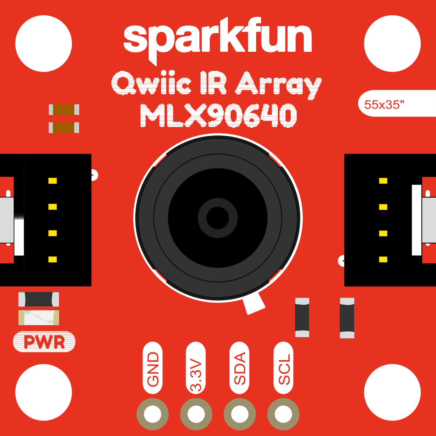
The SparkFun IR Array Breakout with a 55 Degree Field of View (FOV) featuring the MLX90640 is an advanced infrared thermal imaging sensor. This component is capable of detecting and measuring temperature distributions across a wide area, which allows it to serve as the core for thermal cameras or for non-contact temperature measurement systems. Its ease of integration with microcontroller platforms, particularly those with Qwiic connectivity, makes it a popular choice for hobbyists and professionals working on projects in areas such as security systems, environmental monitoring, HVAC control, and health-related devices.

Explore Projects Built with SparkFun IR Array Breakout - 55 Degree FOV, MLX90640 (Qwiic)

Use Cirkit Designer to design, explore, and prototype these projects online. Some projects support real-time simulation. Click "Open Project" to start designing instantly!
Arduino Nano-Powered PID Line Following Robot with Reflectance Sensor Array and Dual Motor Driver
Image of Line following bot: A project utilizing SparkFun IR Array Breakout - 55 Degree FOV, MLX90640 (Qwiic) in a practical application
This circuit is designed for an advanced line-following robot that uses a QTRX-HD-07RC Reflectance Sensor Array for line sensing and a Motor Driver 1A Dual TB6612FNG to control two DC Mini Metal Gear Motors. The Arduino Nano serves as the microcontroller, running a PID control algorithm to adjust the motor speeds for precise tracking. Power is supplied by a 5V battery for the logic and a 12V battery for the motor driver.
Cirkit Designer LogoOpen Project in Cirkit Designer
Battery-Powered Smart Sensor Hub with Adafruit QT Py RP2040
Image of wearable final: A project utilizing SparkFun IR Array Breakout - 55 Degree FOV, MLX90640 (Qwiic) in a practical application
This circuit features an Adafruit QT Py RP2040 microcontroller interfaced with an APDS9960 proximity sensor, an MPU6050 accelerometer and gyroscope, and an OLED display via I2C communication. It also includes a buzzer controlled by the microcontroller and is powered by a 3.7V LiPo battery with a toggle switch for power control.
Cirkit Designer LogoOpen Project in Cirkit Designer
ESP32-CAM and IR Sensor Interface with USB UART Communication
Image of esp32cam parking: A project utilizing SparkFun IR Array Breakout - 55 Degree FOV, MLX90640 (Qwiic) in a practical application
This circuit features an ESP32 CAM module interfaced with an IR sensor and a SparkFun USB UART Breakout board. The ESP32 CAM provides power to the IR sensor and receives its output signal, likely for processing or triggering camera actions based on IR detection. The USB UART Breakout board is connected to the ESP32 CAM for serial communication, enabling programming, debugging, or data exchange with a computer.
Cirkit Designer LogoOpen Project in Cirkit Designer
Adafruit MPU6050 and VL6180X Sensor Interface with Servo Control
Image of wire: A project utilizing SparkFun IR Array Breakout - 55 Degree FOV, MLX90640 (Qwiic) in a practical application
This circuit features an Adafruit QT Py microcontroller interfaced with an Adafruit MPU6050 6-axis accelerometer/gyroscope and an Adafruit VL6180X Time of Flight (ToF) distance sensor, both connected via I2C communication. The QT Py also controls a Servomotor SG90, likely for physical actuation based on sensor inputs. The embedded code initializes the sensors, reads their data, and outputs the readings to a serial monitor, with the potential for motion control based on the sensor feedback.
Cirkit Designer LogoOpen Project in Cirkit Designer

Explore Projects Built with SparkFun IR Array Breakout - 55 Degree FOV, MLX90640 (Qwiic)

Use Cirkit Designer to design, explore, and prototype these projects online. Some projects support real-time simulation. Click "Open Project" to start designing instantly!
Image of Line following bot: A project utilizing SparkFun IR Array Breakout - 55 Degree FOV, MLX90640 (Qwiic) in a practical application
Arduino Nano-Powered PID Line Following Robot with Reflectance Sensor Array and Dual Motor Driver
This circuit is designed for an advanced line-following robot that uses a QTRX-HD-07RC Reflectance Sensor Array for line sensing and a Motor Driver 1A Dual TB6612FNG to control two DC Mini Metal Gear Motors. The Arduino Nano serves as the microcontroller, running a PID control algorithm to adjust the motor speeds for precise tracking. Power is supplied by a 5V battery for the logic and a 12V battery for the motor driver.
Cirkit Designer LogoOpen Project in Cirkit Designer
Image of wearable final: A project utilizing SparkFun IR Array Breakout - 55 Degree FOV, MLX90640 (Qwiic) in a practical application
Battery-Powered Smart Sensor Hub with Adafruit QT Py RP2040
This circuit features an Adafruit QT Py RP2040 microcontroller interfaced with an APDS9960 proximity sensor, an MPU6050 accelerometer and gyroscope, and an OLED display via I2C communication. It also includes a buzzer controlled by the microcontroller and is powered by a 3.7V LiPo battery with a toggle switch for power control.
Cirkit Designer LogoOpen Project in Cirkit Designer
Image of esp32cam parking: A project utilizing SparkFun IR Array Breakout - 55 Degree FOV, MLX90640 (Qwiic) in a practical application
ESP32-CAM and IR Sensor Interface with USB UART Communication
This circuit features an ESP32 CAM module interfaced with an IR sensor and a SparkFun USB UART Breakout board. The ESP32 CAM provides power to the IR sensor and receives its output signal, likely for processing or triggering camera actions based on IR detection. The USB UART Breakout board is connected to the ESP32 CAM for serial communication, enabling programming, debugging, or data exchange with a computer.
Cirkit Designer LogoOpen Project in Cirkit Designer
Image of wire: A project utilizing SparkFun IR Array Breakout - 55 Degree FOV, MLX90640 (Qwiic) in a practical application
Adafruit MPU6050 and VL6180X Sensor Interface with Servo Control
This circuit features an Adafruit QT Py microcontroller interfaced with an Adafruit MPU6050 6-axis accelerometer/gyroscope and an Adafruit VL6180X Time of Flight (ToF) distance sensor, both connected via I2C communication. The QT Py also controls a Servomotor SG90, likely for physical actuation based on sensor inputs. The embedded code initializes the sensors, reads their data, and outputs the readings to a serial monitor, with the potential for motion control based on the sensor feedback.
Cirkit Designer LogoOpen Project in Cirkit Designer

Technical Specifications

Key Technical Details

  • Sensor Type: Far infrared thermal sensor array
  • Field of View (FOV): 55 degrees
  • Resolution: 32x24 pixels
  • Measurement Range: -40°C to 300°C
  • Refresh Rate: Up to 64Hz
  • Interface: I2C (Qwiic compatible)
  • Supply Voltage: 3V to 3.6V
  • Current Consumption: 23mA (typical)

Pin Configuration and Descriptions

Pin Number Pin Name Description
1 VDD Power supply (3V to 3.6V)
2 GND Ground
3 SDA I2C Data
4 SCL I2C Clock
5 INT Interrupt (active low, open-drain)
6 3V3 3.3V output from the onboard voltage regulator

Usage Instructions

Integration with a Circuit

To use the MLX90640 IR Array Breakout in a circuit:

  1. Connect the VDD pin to a 3V to 3.6V power supply.
  2. Connect the GND pin to the ground of your power supply.
  3. Connect the SDA and SCL pins to the I2C data and clock lines of your microcontroller, respectively.
  4. If interrupt functionality is required, connect the INT pin to an interrupt-capable GPIO on your microcontroller.
  5. Optionally, use the 3V3 pin if other components in your system require a 3.3V supply from the breakout board.

Best Practices

  • Ensure that the power supply is stable and within the specified voltage range.
  • Use pull-up resistors on the I2C lines if they are not already present on your microcontroller board.
  • Avoid exposing the sensor to extreme temperatures that exceed its measurement range.
  • Keep the sensor away from direct sunlight and other strong infrared sources to prevent inaccurate readings.

Troubleshooting and FAQs

Common Issues

  • No Data on I2C: Check connections and ensure that the correct I2C address is being used. Also, verify that pull-up resistors are installed if needed.
  • Inaccurate Temperature Readings: Ensure that the sensor is not exposed to direct sunlight or reflective surfaces that could skew the readings.

Solutions and Tips

  • If you encounter issues with the I2C communication, use a logic analyzer to check the data and clock signals.
  • For best accuracy, calibrate the sensor in the environment where it will be used.

FAQs

Q: Can the MLX90640 be used with an Arduino? A: Yes, it can be easily connected to an Arduino using the I2C interface.

Q: Does the sensor require calibration? A: The sensor comes factory-calibrated, but for precise applications, additional calibration may be necessary.

Q: What is the purpose of the INT pin? A: The INT pin can be used to trigger an interrupt in your microcontroller when new data is available to read.

Example Code for Arduino UNO

Below is a simple example code to read data from the MLX90640 sensor using an Arduino UNO. This code assumes the use of the standard Wire library for I2C communication and a compatible MLX90640 library.

#include <Wire.h>
#include <Adafruit_MLX90640.h>

Adafruit_MLX90640 mlx;

void setup() {
  Serial.begin(9600);
  Serial.println("MLX90640 test");

  // Begin communication with the sensor
  if (!mlx.begin()) {
    Serial.println("Failed to find MLX90640 sensor");
    while (1);
  }
  Serial.println("MLX90640 Found!");
}

void loop() {
  float mlx90640Frame[32 * 24]; // Buffer to store temperature readings

  // Trigger a new measurement
  if (mlx.getFrame(mlx90640Frame) == 0) {
    for (int i = 0; i < 32 * 24; i++) {
      // Print temperature values in a grid format
      Serial.print(mlx90640Frame[i], 2);
      Serial.print(" ");
      if ((i + 1) % 32 == 0) {
        Serial.println();
      }
    }
    Serial.println();
  } else {
    Serial.println("Failed to read frame");
  }

  delay(1000); // Wait for a second before reading again
}

Ensure that you have installed the necessary libraries before uploading this code to your Arduino UNO. The example code provided is for demonstration purposes and may require modifications to work with your specific setup.