How to Use PRIMARY PCB: Examples, Pinouts, and Specs
Introduction
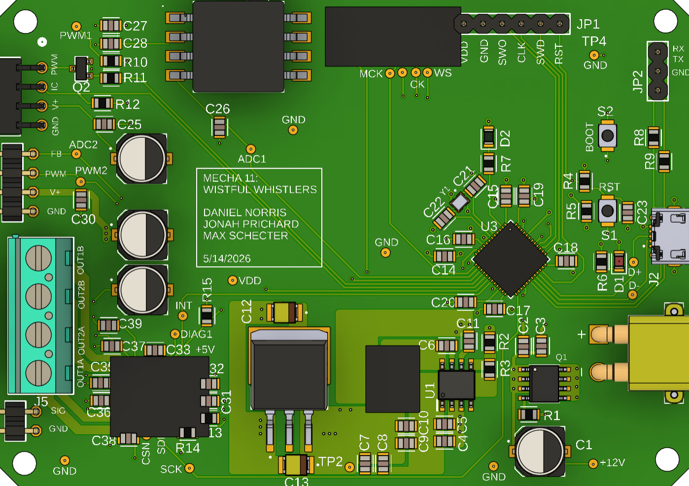
The Primary PCB by Whistful Whistles serves as the main platform for mounting and connecting electronic components. It provides both electrical pathways and mechanical support, ensuring the proper functioning of the circuit. This versatile component is essential in a wide range of electronic devices, from consumer electronics to industrial systems.
Explore Projects Built with PRIMARY PCB
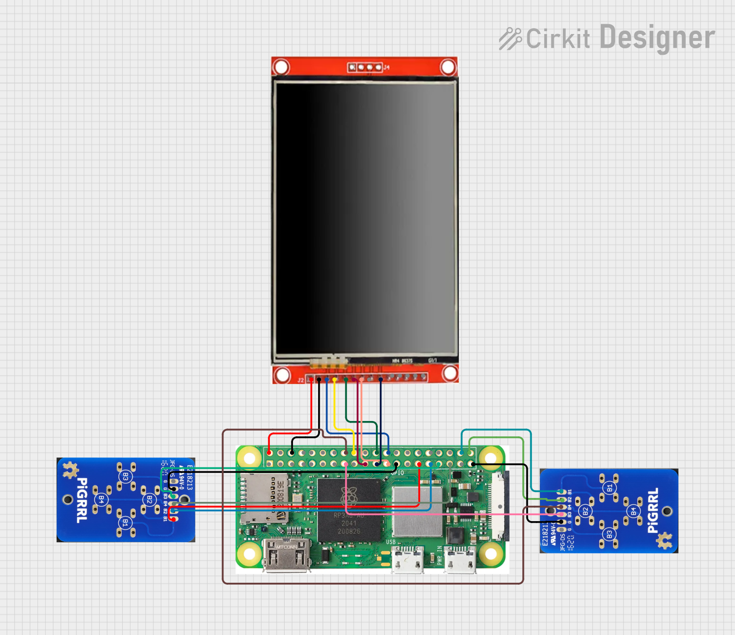
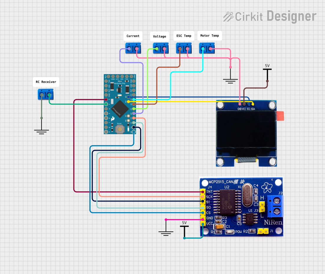

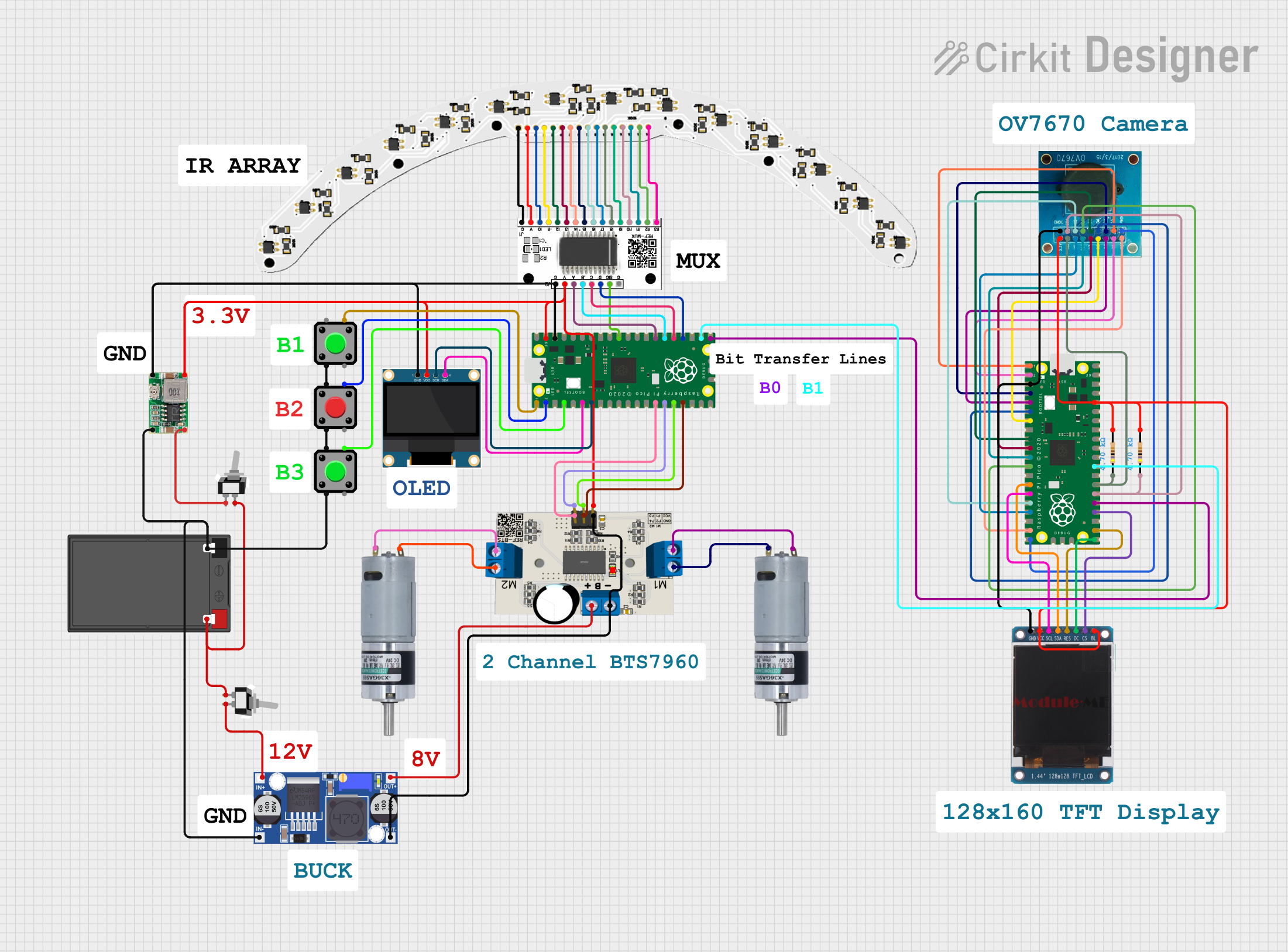
Explore Projects Built with PRIMARY PCB
Common Applications and Use Cases
- Consumer Electronics: Smartphones, laptops, and home appliances.
- Industrial Systems: Control panels, automation systems, and robotics.
- Prototyping: Ideal for testing and developing new electronic designs.
- IoT Devices: Serves as the backbone for sensors, microcontrollers, and communication modules.
Technical Specifications
The Primary PCB is designed to meet the needs of modern electronic systems. Below are its key technical details:
General Specifications
| Parameter | Value |
|---|---|
| Manufacturer | Whistful Whistles |
| Material | FR4 (Flame Retardant 4) |
| Layers | 2-layer or 4-layer options |
| Copper Thickness | 1 oz/ft² (standard) |
| Board Thickness | 1.6 mm |
| Surface Finish | HASL (Hot Air Solder Leveling) |
| Solder Mask Color | Green (default) |
| Operating Temperature | -40°C to +85°C |
Pin Configuration and Descriptions
While the Primary PCB does not have traditional "pins," it features pads and vias for component mounting and interconnections. Below is a description of key elements:
| Element | Description |
|---|---|
| Pads | Copper areas for soldering components such as resistors, capacitors, etc. |
| Vias | Holes plated with copper to connect layers of the PCB. |
| Traces | Copper pathways that carry electrical signals between components. |
| Mounting Holes | Non-conductive holes for securing the PCB to an enclosure or chassis. |
Usage Instructions
To use the Primary PCB effectively, follow these steps and best practices:
Step 1: Design the Circuit
- Use PCB design software (e.g., KiCad, Eagle, or Altium Designer) to create the schematic and layout.
- Ensure proper trace width and spacing based on current requirements and voltage levels.
Step 2: Component Placement
- Place components logically to minimize trace lengths and avoid signal interference.
- Group related components (e.g., resistors and capacitors for a microcontroller) together.
Step 3: Soldering Components
- Use a soldering iron or reflow soldering process to attach components to the PCB.
- Ensure proper solder joints to avoid cold soldering or short circuits.
Step 4: Testing and Debugging
- After assembly, test the PCB for continuity and functionality using a multimeter or oscilloscope.
- Verify that all components are functioning as intended.
Important Considerations
- Power Supply: Ensure the PCB can handle the required voltage and current without overheating.
- Signal Integrity: Use ground planes and proper trace routing to reduce noise and interference.
- Thermal Management: For high-power applications, include thermal vias or heat sinks.
Example: Connecting to an Arduino UNO
The Primary PCB can be used to create custom shields for the Arduino UNO. Below is an example of how to connect an LED and resistor to the PCB and control it using the Arduino:
Circuit Diagram
- Connect the LED's anode to a digital pin (e.g., D13) via a 220-ohm resistor.
- Connect the LED's cathode to the PCB's ground plane.
Arduino Code
// Example code to blink an LED connected to the Primary PCB
// Ensure the LED is connected to pin 13 and ground.

void setup() {
  pinMode(13, OUTPUT); // Set pin 13 as an output
}

void loop() {
  digitalWrite(13, HIGH); // Turn the LED on
  delay(1000);            // Wait for 1 second
  digitalWrite(13, LOW);  // Turn the LED off
  delay(1000);            // Wait for 1 second
}
Troubleshooting and FAQs
Common Issues
Short Circuits
- Cause: Solder bridges between adjacent pads or traces.
- Solution: Inspect the PCB under a magnifying glass and remove excess solder with a solder wick.
Open Circuits
- Cause: Poor solder joints or broken traces.
- Solution: Re-solder the affected area or use a jumper wire to repair broken traces.
Overheating
- Cause: Excessive current or insufficient thermal management.
- Solution: Use thicker copper layers or add heat sinks for high-power components.
Signal Noise
- Cause: Poor grounding or improper trace routing.
- Solution: Add ground planes and ensure proper trace spacing.
FAQs
Q: Can the Primary PCB handle high-frequency signals?
A: Yes, but ensure proper trace impedance matching and use ground planes to minimize noise.
Q: What is the maximum current the PCB can handle?
A: This depends on the trace width and copper thickness. For 1 oz/ft² copper, a 1 mm-wide trace can handle approximately 2.3 A.
Q: Can I use the PCB in outdoor environments?
A: The PCB is rated for -40°C to +85°C. For outdoor use, consider conformal coating to protect against moisture and dust.
By following this documentation, you can effectively utilize the Primary PCB by Whistful Whistles in your electronic projects.