How to Use 테무 릴레이 8개 버튼: Examples, Pinouts, and Specs
Introduction
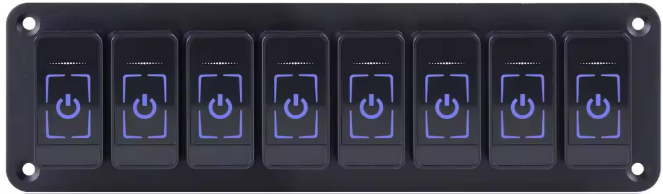
The 테무 릴레이 8개 버튼 is an 8-channel relay module designed for controlling high-power devices using low-power control signals. Manufactured by 테무, this module is ideal for applications requiring multiple relays, such as home automation, industrial control systems, and robotics. Each relay can be independently controlled, making it versatile for a wide range of projects.
This module is commonly used with microcontrollers like Arduino, Raspberry Pi, and other development boards to switch devices such as lights, motors, and appliances.
Explore Projects Built with 테무 릴레이 8개 버튼


Explore Projects Built with 테무 릴레이 8개 버튼
Technical Specifications
- Manufacturer: 테무
- Part ID: 테무 릴레이 8개 버튼
- Number of Channels: 8
- Relay Type: Electromechanical
- Control Voltage: 5V DC
- Trigger Current: 15-20mA per channel
- Relay Output: Supports AC (250V/10A) or DC (30V/10A)
- Isolation: Optocoupler isolation for safe operation
- Dimensions: 138mm x 56mm x 18mm
- Weight: ~120g
Pin Configuration and Descriptions
The 테무 릴레이 8개 버튼 module has the following pin layout:
Control Pins
| Pin Name | Description |
|---|---|
| IN1 | Control signal for Relay 1 |
| IN2 | Control signal for Relay 2 |
| IN3 | Control signal for Relay 3 |
| IN4 | Control signal for Relay 4 |
| IN5 | Control signal for Relay 5 |
| IN6 | Control signal for Relay 6 |
| IN7 | Control signal for Relay 7 |
| IN8 | Control signal for Relay 8 |
| GND | Ground connection |
| VCC | 5V power supply for the module |
Relay Output Terminals
Each relay has three output terminals:
| Terminal Name | Description |
|---|---|
| COM | Common terminal |
| NO | Normally Open terminal |
| NC | Normally Closed terminal |
- COM: Connects to the common line of the circuit.
- NO: Connects to the load when the relay is activated.
- NC: Connects to the load when the relay is deactivated.
Usage Instructions
How to Use the Component in a Circuit
- Power the Module: Connect the VCC pin to a 5V DC power source and the GND pin to ground.
- Connect Control Signals: Use digital output pins from a microcontroller (e.g., Arduino) to connect to the IN1-IN8 pins. Each pin controls one relay.
- Connect the Load:
- For devices that should turn on when the relay is activated, connect the device between the COM and NO terminals.
- For devices that should turn off when the relay is activated, connect the device between the COM and NC terminals.
- Write Control Code: Use the microcontroller to send HIGH or LOW signals to the IN pins to activate or deactivate the relays.
Important Considerations and Best Practices
- Ensure the total current drawn by the relays does not exceed the power supply's capacity.
- Use proper insulation and safety precautions when working with high-voltage AC loads.
- Avoid switching loads that exceed the relay's rated capacity (250V AC/10A or 30V DC/10A).
- Use optocoupler isolation to protect the microcontroller from voltage spikes.
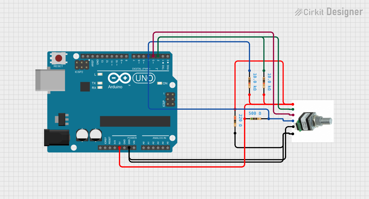
Example Code for Arduino UNO
Below is an example code to control the 테무 릴레이 8개 버튼 module using an Arduino UNO:
// Example code to control the 테무 릴레이 8개 버튼 module with Arduino UNO

// Define relay control pins
#define RELAY1 2
#define RELAY2 3
#define RELAY3 4
#define RELAY4 5
#define RELAY5 6
#define RELAY6 7
#define RELAY7 8
#define RELAY8 9

void setup() {
  // Set relay pins as output
  pinMode(RELAY1, OUTPUT);
  pinMode(RELAY2, OUTPUT);
  pinMode(RELAY3, OUTPUT);
  pinMode(RELAY4, OUTPUT);
  pinMode(RELAY5, OUTPUT);
  pinMode(RELAY6, OUTPUT);
  pinMode(RELAY7, OUTPUT);
  pinMode(RELAY8, OUTPUT);

  // Initialize all relays to OFF state
  digitalWrite(RELAY1, LOW);
  digitalWrite(RELAY2, LOW);
  digitalWrite(RELAY3, LOW);
  digitalWrite(RELAY4, LOW);
  digitalWrite(RELAY5, LOW);
  digitalWrite(RELAY6, LOW);
  digitalWrite(RELAY7, LOW);
  digitalWrite(RELAY8, LOW);
}

void loop() {
  // Example: Turn on each relay sequentially with a 1-second delay
  digitalWrite(RELAY1, HIGH); // Turn on Relay 1
  delay(1000);                // Wait for 1 second
  digitalWrite(RELAY1, LOW);  // Turn off Relay 1

  digitalWrite(RELAY2, HIGH); // Turn on Relay 2
  delay(1000);                // Wait for 1 second
  digitalWrite(RELAY2, LOW);  // Turn off Relay 2

  // Repeat for other relays
  digitalWrite(RELAY3, HIGH);
  delay(1000);
  digitalWrite(RELAY3, LOW);

  digitalWrite(RELAY4, HIGH);
  delay(1000);
  digitalWrite(RELAY4, LOW);

  digitalWrite(RELAY5, HIGH);
  delay(1000);
  digitalWrite(RELAY5, LOW);

  digitalWrite(RELAY6, HIGH);
  delay(1000);
  digitalWrite(RELAY6, LOW);

  digitalWrite(RELAY7, HIGH);
  delay(1000);
  digitalWrite(RELAY7, LOW);

  digitalWrite(RELAY8, HIGH);
  delay(1000);
  digitalWrite(RELAY8, LOW);
}
Troubleshooting and FAQs
Common Issues
Relays Not Activating:
- Ensure the VCC and GND pins are properly connected to a 5V power source.
- Verify that the control signals (IN1-IN8) are receiving the correct HIGH/LOW signals.
Microcontroller Resetting:
- This may occur due to insufficient power supply. Use a separate power source for the relay module if needed.
Relay Clicking but Load Not Switching:
- Check the wiring of the COM, NO, and NC terminals.
- Ensure the load does not exceed the relay's rated capacity.
Voltage Spikes or Noise:
- Use a flyback diode across the relay coil to suppress voltage spikes.
- Add capacitors to the power supply lines for noise filtering.
FAQs
Can this module be used with a 3.3V microcontroller?
- Yes, but you may need a level shifter or transistor to ensure proper triggering of the relays.
What is the maximum number of relays I can activate simultaneously?
- You can activate all 8 relays simultaneously, provided your power supply can handle the total current draw.
Is the module safe for high-voltage applications?
- Yes, but always follow proper safety precautions and ensure adequate insulation when working with high-voltage AC loads.
This documentation provides all the necessary details to effectively use the 테무 릴레이 8개 버튼 module in your projects.