Cirkit Designer Logo
Cirkit Designer
Your all-in-one circuit design IDE
Home / 
Component Documentation

How to Use LED Tactile Button Breakout: Examples, Pinouts, and Specs

Image of LED Tactile Button Breakout
Cirkit Designer LogoDesign with LED Tactile Button Breakout in Cirkit Designer

Introduction

The LED Tactile Button Breakout is an electronic component that combines the functionality of a tactile switch with an integrated LED, providing both tactile and visual feedback. This component is ideal for user interfaces where an immediate visual indication of a button press is beneficial, such as in control panels, user input devices, and interactive projects. The LED illuminates upon pressing the button, offering a clear indication of activation.

Explore Projects Built with LED Tactile Button Breakout

Use Cirkit Designer to design, explore, and prototype these projects online. Some projects support real-time simulation. Click "Open Project" to start designing instantly!
Bluetooth-Controlled Multi-Function Arduino Nano Gadget
Image of Copy of Smarttt: A project utilizing LED Tactile Button Breakout in a practical application
This is a portable, microcontroller-driven interactive device featuring Bluetooth connectivity, visual (RGB LED), auditory (loudspeaker), and haptic (vibration motor) feedback, user input (pushbutton), and a rechargeable power system (TP4056 with Li-ion battery).
Cirkit Designer LogoOpen Project in Cirkit Designer
Raspberry Pi Zero Controlled LED and Button Interface
Image of pi-zero-camera: A project utilizing LED Tactile Button Breakout in a practical application
This circuit includes a Raspberry Pi Zero connected to two tactile switches and two LEDs (one green and one orange). The switches are connected to GPIO pins 23 and 16 for input, and the LEDs are connected to GPIO pins 24 and 12 for output, with their other leads connected to ground. The circuit is likely designed for simple input/output interaction with the Raspberry Pi, where the switches can be used to trigger software events, and the LEDs can provide visual feedback.
Cirkit Designer LogoOpen Project in Cirkit Designer
Pushbutton-Controlled Dual-Color LED Circuit with TA6568
Image of polarity detector: A project utilizing LED Tactile Button Breakout in a practical application
This is a pushbutton-controlled LED circuit with a TA6568 chip that likely drives two LEDs (red and green). Each LED is connected to a pushbutton through the TA6568, allowing the user to toggle the state of the LEDs. The circuit is powered by a 3V battery and includes a JST connector for external interfacing.
Cirkit Designer LogoOpen Project in Cirkit Designer
Touch-Interactive Distance Measurement System with Visual and Audio Feedback
Image of DIBH project: A project utilizing LED Tactile Button Breakout in a practical application
This is a microcontroller-based interactive circuit featuring touch and ultrasonic sensors for input, and LEDs, a buzzer, and an OLED display for output. It is powered by a 9V battery with a voltage regulator for stable operation, and includes a toggle switch for power control. The actual behavior of the circuit is determined by the embedded code, which is currently a placeholder for further development.
Cirkit Designer LogoOpen Project in Cirkit Designer

Explore Projects Built with LED Tactile Button Breakout

Use Cirkit Designer to design, explore, and prototype these projects online. Some projects support real-time simulation. Click "Open Project" to start designing instantly!
Image of Copy of Smarttt: A project utilizing LED Tactile Button Breakout in a practical application
Bluetooth-Controlled Multi-Function Arduino Nano Gadget
This is a portable, microcontroller-driven interactive device featuring Bluetooth connectivity, visual (RGB LED), auditory (loudspeaker), and haptic (vibration motor) feedback, user input (pushbutton), and a rechargeable power system (TP4056 with Li-ion battery).
Cirkit Designer LogoOpen Project in Cirkit Designer
Image of pi-zero-camera: A project utilizing LED Tactile Button Breakout in a practical application
Raspberry Pi Zero Controlled LED and Button Interface
This circuit includes a Raspberry Pi Zero connected to two tactile switches and two LEDs (one green and one orange). The switches are connected to GPIO pins 23 and 16 for input, and the LEDs are connected to GPIO pins 24 and 12 for output, with their other leads connected to ground. The circuit is likely designed for simple input/output interaction with the Raspberry Pi, where the switches can be used to trigger software events, and the LEDs can provide visual feedback.
Cirkit Designer LogoOpen Project in Cirkit Designer
Image of polarity detector: A project utilizing LED Tactile Button Breakout in a practical application
Pushbutton-Controlled Dual-Color LED Circuit with TA6568
This is a pushbutton-controlled LED circuit with a TA6568 chip that likely drives two LEDs (red and green). Each LED is connected to a pushbutton through the TA6568, allowing the user to toggle the state of the LEDs. The circuit is powered by a 3V battery and includes a JST connector for external interfacing.
Cirkit Designer LogoOpen Project in Cirkit Designer
Image of DIBH project: A project utilizing LED Tactile Button Breakout in a practical application
Touch-Interactive Distance Measurement System with Visual and Audio Feedback
This is a microcontroller-based interactive circuit featuring touch and ultrasonic sensors for input, and LEDs, a buzzer, and an OLED display for output. It is powered by a 9V battery with a voltage regulator for stable operation, and includes a toggle switch for power control. The actual behavior of the circuit is determined by the embedded code, which is currently a placeholder for further development.
Cirkit Designer LogoOpen Project in Cirkit Designer

Technical Specifications

Key Technical Details

  • Voltage Rating for LED: Typically 3.3V to 5V
  • Current Rating for LED: 20mA (standard LED current)
  • Switch Rating: 50mA at 12V DC
  • LED Color: (Common colors include red, green, blue, yellow, white)
  • Bounce Time: <10ms
  • Operating Force: Approximately 250g to 350g
  • Life Expectancy: 100,000 to 1,000,000 cycles

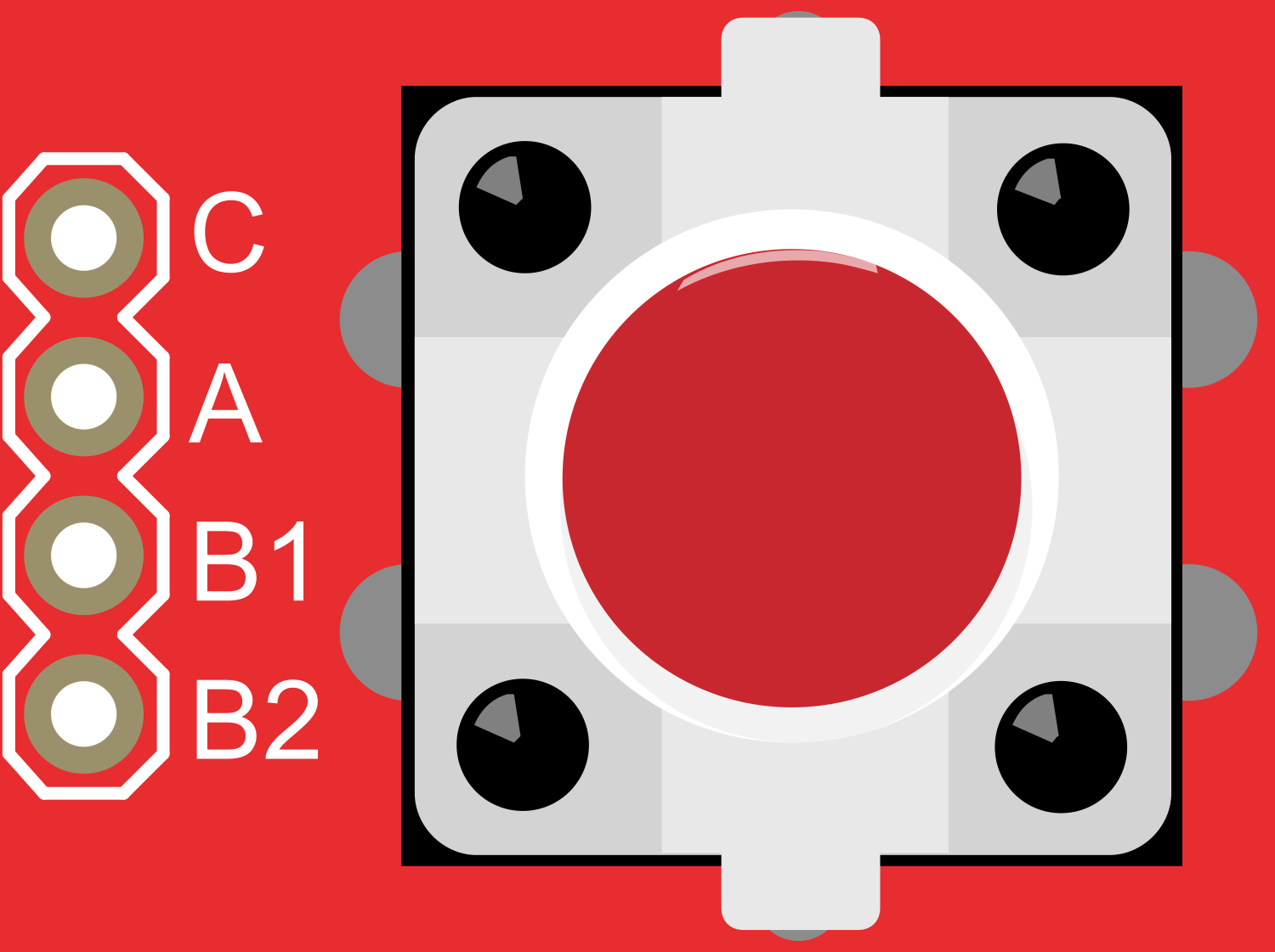
Pin Configuration and Descriptions

Pin Number Description Notes
1 LED Anode (+) Connect to positive voltage via resistor
2 LED Cathode (-) Connect to ground
3 Button Output Connect to digital input on microcontroller
4 Button Ground Connect to ground

Usage Instructions

Connecting to a Circuit

  1. LED Connection:

    • Connect the LED anode (pin 1) to a digital output pin on the microcontroller through a current-limiting resistor.
    • Connect the LED cathode (pin 2) to the ground.
  2. Button Connection:

    • Connect the button output (pin 3) to a digital input pin on the microcontroller.
    • Connect the button ground (pin 4) to the ground.

Important Considerations and Best Practices

  • Current-Limiting Resistor: Always use a current-limiting resistor with the LED to prevent damage. A typical value is 220 ohms for a 5V supply.
  • Debounce: Implement software debouncing to handle the mechanical bounce of the tactile switch.
  • Input Pull-up Resistor: Use the internal pull-up resistor feature of the microcontroller if available to simplify the circuit.

Example Code for Arduino UNO

const int buttonPin = 2; // Button output connected to digital pin 2
const int ledPin = 13;   // LED anode connected to digital pin 13 through a resistor

void setup() {
  pinMode(ledPin, OUTPUT);      // Initialize the LED pin as an output
  pinMode(buttonPin, INPUT);    // Initialize the button pin as an input
}

void loop() {
  int buttonState = digitalRead(buttonPin); // Read the state of the button
  if (buttonState == HIGH) {
    // If the button is pressed, turn on the LED
    digitalWrite(ledPin, HIGH);
  } else {
    // If the button is not pressed, turn off the LED
    digitalWrite(ledPin, LOW);
  }
}

Troubleshooting and FAQs

Common Issues

  • LED Not Lighting Up:

    • Check if the LED is connected correctly with the correct polarity.
    • Ensure the current-limiting resistor is properly connected and of the correct value.
    • Verify that the microcontroller's output pin is configured correctly and functioning.
  • Button Not Responding:

    • Confirm that the button's output pin is connected to the correct microcontroller pin.
    • Check for a secure ground connection for the button.
    • Ensure that the microcontroller's input pin is set up correctly in the code.

Solutions and Tips for Troubleshooting

  • Use a Multimeter: Check for continuity and correct voltages at various points in the circuit.
  • Isolate the Problem: Test the LED and button separately to determine which part may be at fault.
  • Code Verification: Double-check the code for any errors or misconfigurations, particularly pin assignments.

FAQs

Q: Can I use a different voltage for the LED? A: Yes, but ensure you adjust the current-limiting resistor value accordingly to maintain the proper current through the LED.

Q: How can I change the LED color? A: The LED color is fixed based on the component you purchase. To change the color, you would need to use a different LED Tactile Button Breakout with the desired LED color.

Q: What is the purpose of the current-limiting resistor? A: The resistor limits the current flowing through the LED to prevent it from burning out due to excessive current.

Q: Can I use this component with a microcontroller other than Arduino UNO? A: Yes, the LED Tactile Button Breakout can be used with any microcontroller that has compatible digital I/O pins. Adjust the code and connections accordingly.