
How to Use ST-GYRO-PR: Examples, Pinouts, and Specs
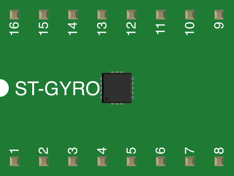
 Design with ST-GYRO-PR in Cirkit Designer
Introduction
The ST-GYRO-PR is a precision gyroscope sensor designed to measure angular velocity with high accuracy. It provides real-time data for motion tracking and orientation detection, making it an essential component in applications such as robotics, drones, smartphones, and gaming devices. Its compact design and reliable performance make it suitable for both consumer and industrial-grade projects.
Explore Projects Built with ST-GYRO-PR
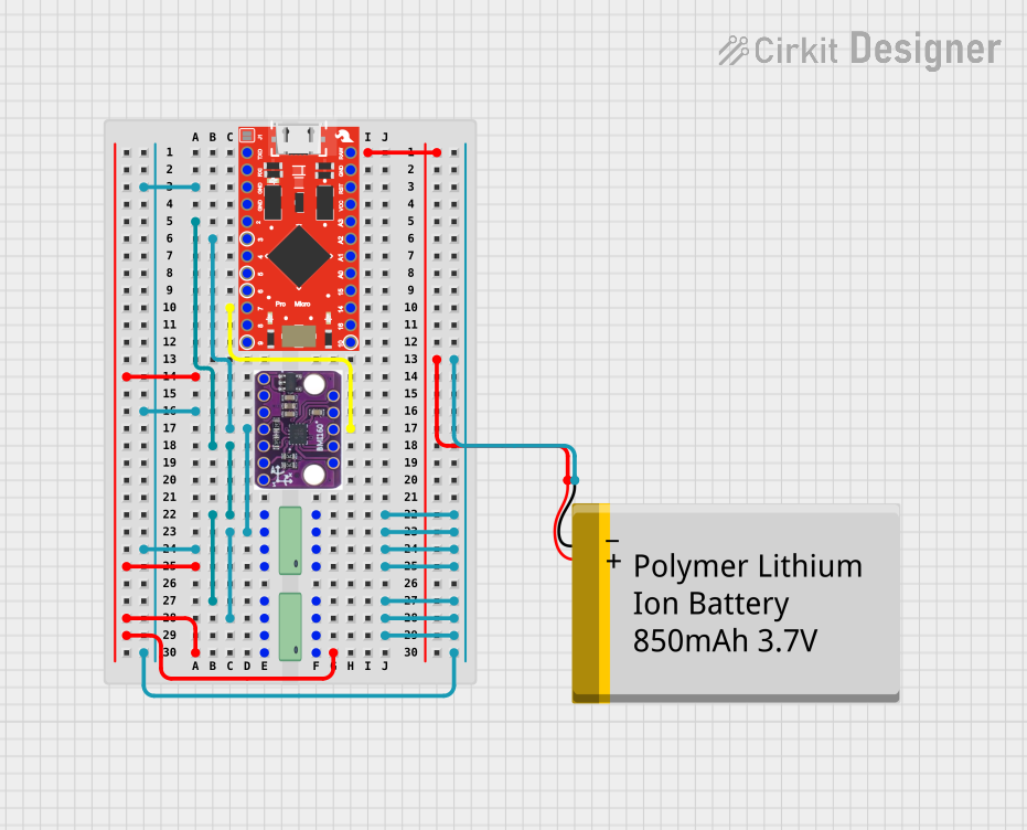 Open Project in Cirkit Designer
 Open Project in Cirkit Designer
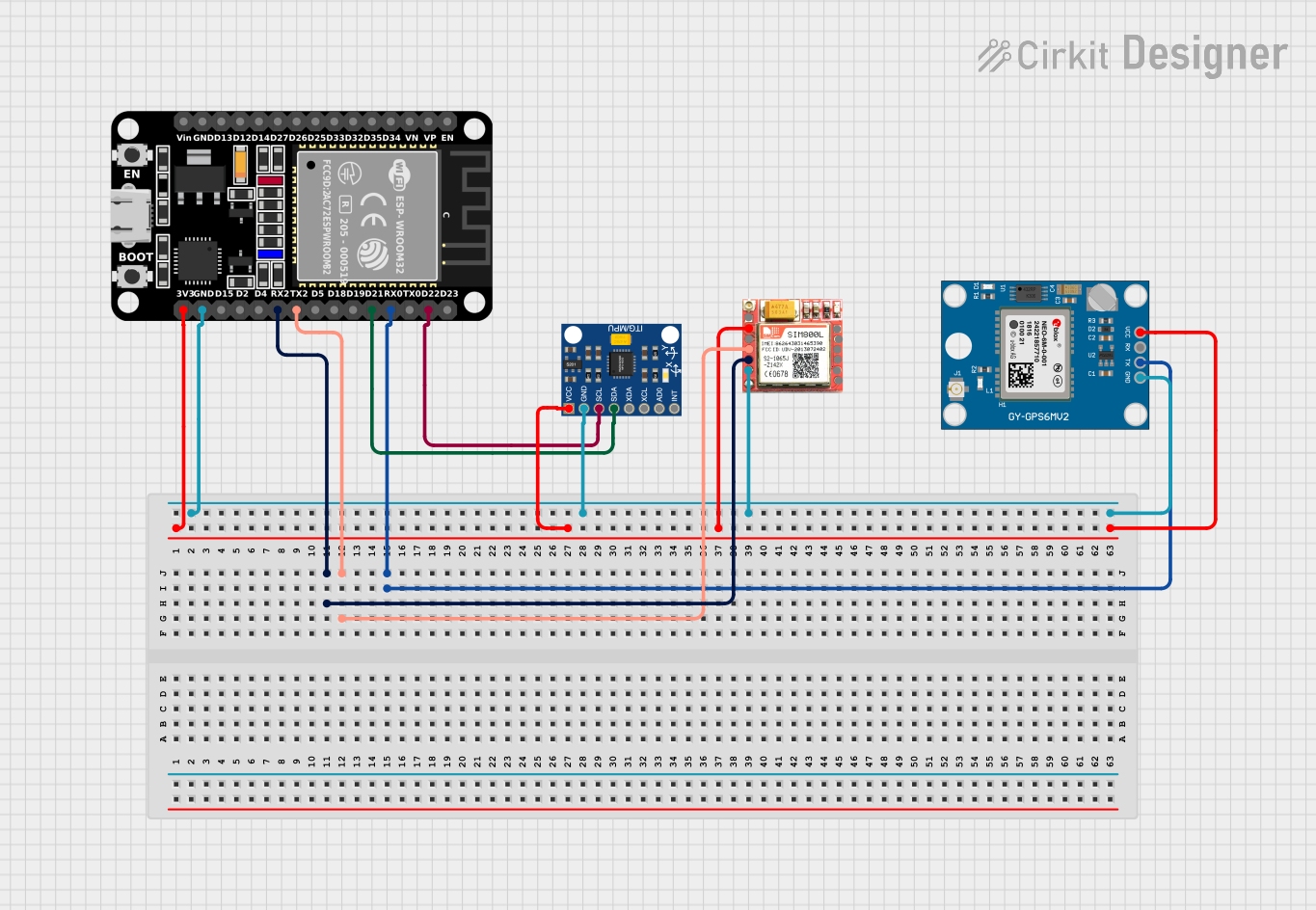 Open Project in Cirkit Designer
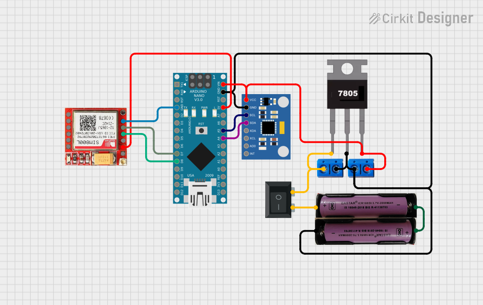 Open Project in Cirkit Designer
Explore Projects Built with ST-GYRO-PR
Open Project in Cirkit DesignerOpen Project in Cirkit DesignerOpen Project in Cirkit DesignerOpen Project in Cirkit DesignerCommon Applications:
- Robotics: For navigation and balance control.
- Drones: To stabilize flight and enable precise maneuvering.
- Smartphones: For screen orientation and motion-based gaming.
- Wearable Devices: For fitness tracking and gesture recognition.
- Automotive Systems: For stability control and navigation assistance.
Technical Specifications
The following table outlines the key technical details of the ST-GYRO-PR:
| Parameter | Value |
|---|---|
| Operating Voltage | 3.3V to 5V |
| Angular Velocity Range | ±250, ±500, ±1000, ±2000 °/s |
| Sensitivity | Configurable (e.g., 131 LSB/°/s) |
| Communication Protocol | I2C, SPI |
| Operating Temperature | -40°C to +85°C |
| Dimensions | 3mm x 3mm x 1mm |
| Power Consumption | 3.6 mA (active mode) |
Pin Configuration
The ST-GYRO-PR has the following pinout:
| Pin | Name | Description |
|---|---|---|
| 1 | VCC | Power supply (3.3V to 5V) |
| 2 | GND | Ground |
| 3 | SCL | Serial Clock Line for I2C communication |
| 4 | SDA | Serial Data Line for I2C communication |
| 5 | CS | Chip Select for SPI communication (active low) |
| 6 | INT | Interrupt pin for motion detection or data readiness |
Usage Instructions
Connecting the ST-GYRO-PR to an Arduino UNO
To use the ST-GYRO-PR with an Arduino UNO, follow these steps:
Wiring:
- Connect the VCC pin of the sensor to the 3.3V or 5V pin on the Arduino.
- Connect the GND pin of the sensor to the GND pin on the Arduino.
- Connect the SCL pin of the sensor to the A5 pin on the Arduino (I2C clock line).
- Connect the SDA pin of the sensor to the A4 pin on the Arduino (I2C data line).
Install Required Libraries:
- Use the Arduino IDE Library Manager to install the
Wirelibrary (pre-installed in most cases). - Optionally, install a gyroscope-specific library for easier data handling.
- Use the Arduino IDE Library Manager to install the
Sample Code: Below is an example code snippet to read angular velocity data from the ST-GYRO-PR using I2C:
#include <Wire.h>

#define GYRO_ADDRESS 0x68 // Replace with the actual I2C address of the sensor

void setup() {
  Wire.begin(); // Initialize I2C communication
  Serial.begin(9600); // Start serial communication for debugging

  // Initialize the gyroscope
  Wire.beginTransmission(GYRO_ADDRESS);
  Wire.write(0x6B); // Power management register
  Wire.write(0x00); // Wake up the sensor
  Wire.endTransmission();
}

void loop() {
  int16_t gyroX, gyroY, gyroZ;

  // Request data from the gyroscope
  Wire.beginTransmission(GYRO_ADDRESS);
  Wire.write(0x43); // Starting register for gyro data
  Wire.endTransmission(false);
  Wire.requestFrom(GYRO_ADDRESS, 6, true); // Request 6 bytes of data

  // Read the data
  gyroX = (Wire.read() << 8) | Wire.read(); // Combine high and low bytes
  gyroY = (Wire.read() << 8) | Wire.read();
  gyroZ = (Wire.read() << 8) | Wire.read();

  // Print the angular velocity values
  Serial.print("Gyro X: ");
  Serial.print(gyroX);
  Serial.print(" | Gyro Y: ");
  Serial.print(gyroY);
  Serial.print(" | Gyro Z: ");
  Serial.println(gyroZ);

  delay(500); // Delay for readability
}
Important Considerations:
- Power Supply: Ensure the sensor is powered within its operating voltage range (3.3V to 5V).
- I2C Address: The default I2C address is
0x68, but it may vary depending on the specific module. Check the datasheet or module documentation. - Mounting Orientation: Properly align the sensor to match the desired axes of measurement.
- Noise Filtering: Use software filtering or hardware damping to reduce noise in high-vibration environments.
Troubleshooting and FAQs
Common Issues:
No Data Output:
- Cause: Incorrect wiring or I2C address mismatch.
- Solution: Double-check the connections and verify the I2C address of the sensor.
Inconsistent Readings:
- Cause: Excessive noise or improper mounting.
- Solution: Use vibration-damping materials and ensure the sensor is securely mounted.
Sensor Not Detected:
- Cause: Faulty sensor or incorrect initialization.
- Solution: Verify the sensor's power supply and recheck the initialization code.
FAQs:
Q: Can the ST-GYRO-PR be used with a 5V microcontroller?
- A: Yes, the sensor supports a 3.3V to 5V operating range, making it compatible with 5V microcontrollers like the Arduino UNO.
Q: How do I change the sensitivity of the sensor?
- A: The sensitivity can be configured by writing to the appropriate control register. Refer to the sensor's datasheet for detailed instructions.
Q: Can I use SPI instead of I2C?
- A: Yes, the ST-GYRO-PR supports both I2C and SPI communication. Use the CS pin to enable SPI mode.
By following this documentation, you can effectively integrate the ST-GYRO-PR into your projects for precise motion tracking and orientation detection.