How to Use Lt 1528: Examples, Pinouts, and Specs
Introduction
The LT1528 is a high-efficiency, low-noise, adjustable voltage regulator integrated circuit (IC) designed to deliver high current outputs with excellent line and load regulation. This component is ideal for applications requiring a stable voltage supply with significant current demand, such as power amplifiers, motor drivers, and high-performance microprocessors.
Explore Projects Built with Lt 1528

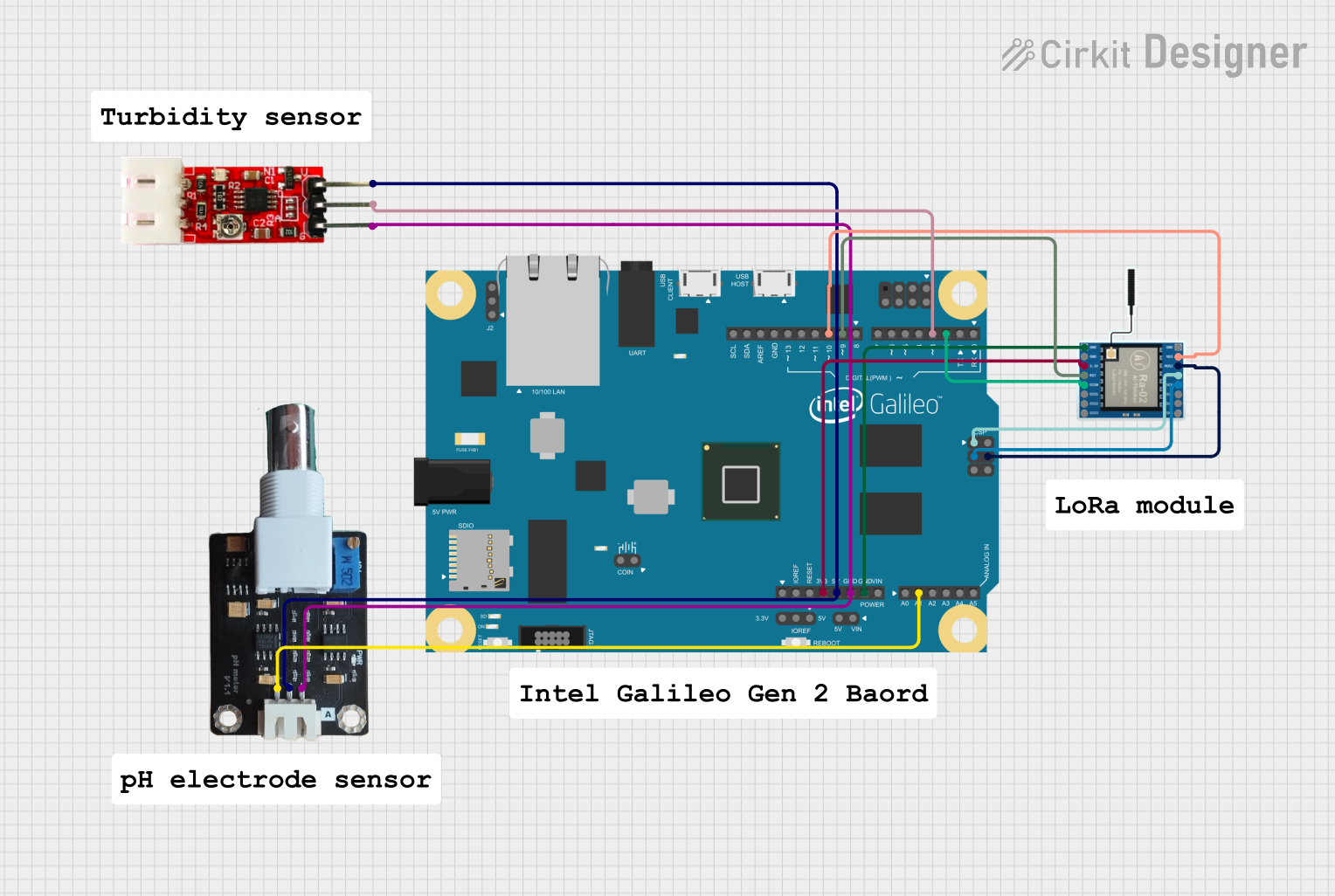
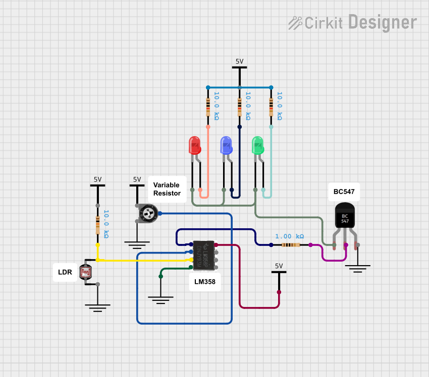
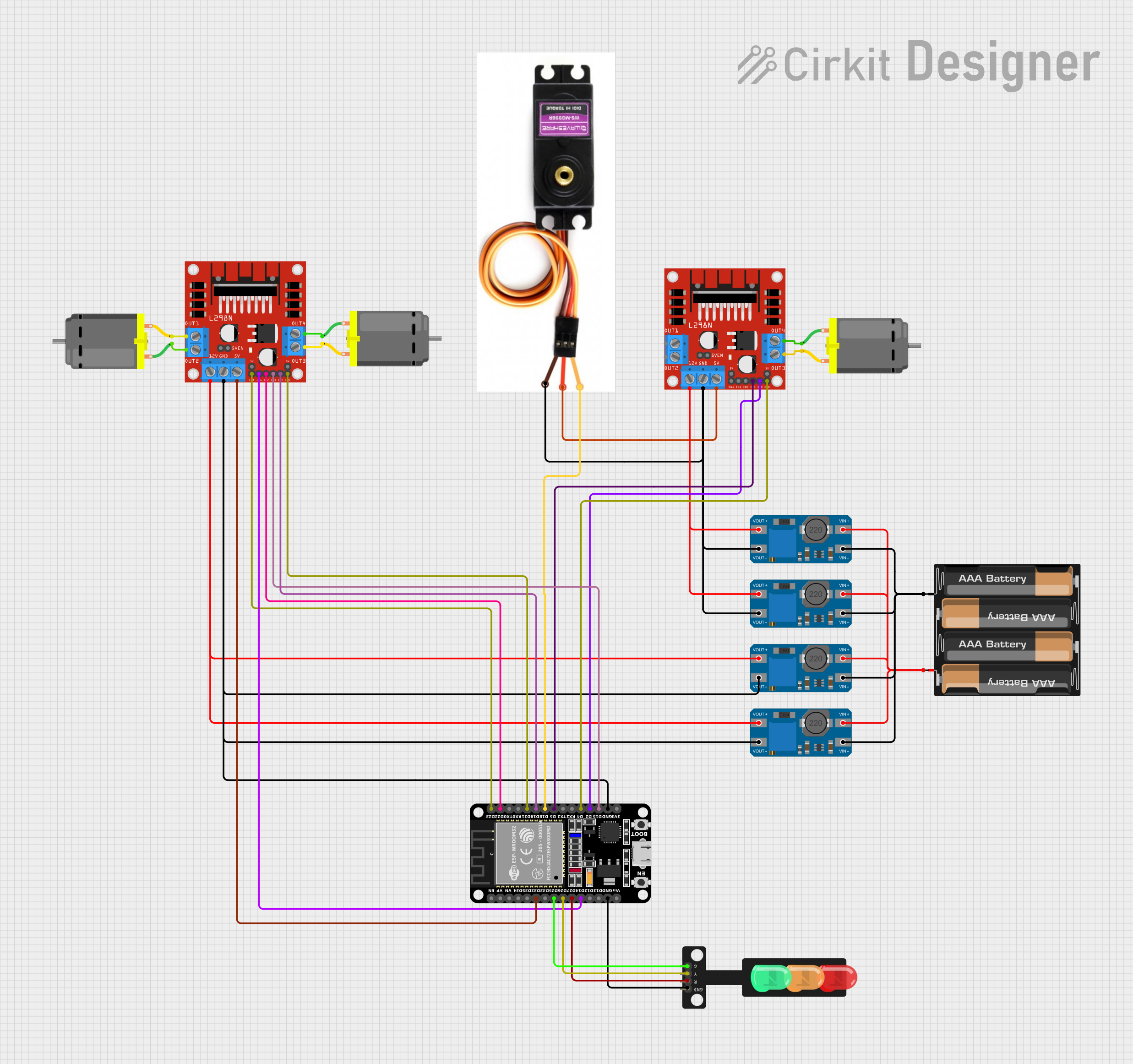
Explore Projects Built with Lt 1528
Common Applications and Use Cases
- Power supplies for microprocessors and digital systems
- Battery chargers
- Post-regulation for switching supplies
- High-current linear regulators
Technical Specifications
Key Technical Details
- Output Voltage Range: Adjustable from 1.22V to 20V
- Output Current: Up to 3A
- Dropout Voltage: Typically 0.6V at 3A
- Line Regulation: Typically 0.005%/V
- Load Regulation: Typically 0.05%
- Operating Temperature Range: -40°C to +125°C
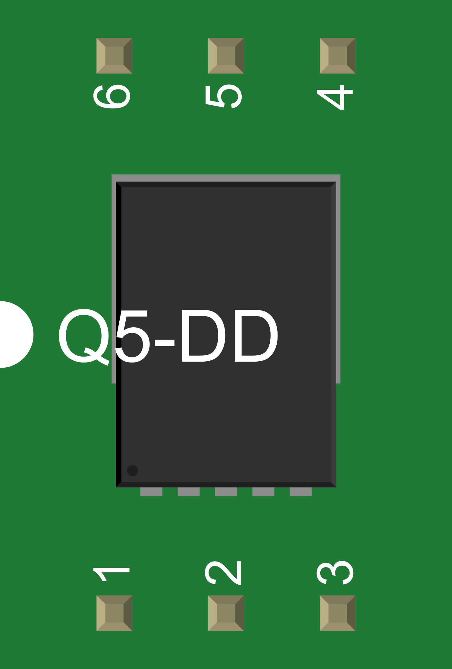
Pin Configuration and Descriptions
| Pin Number | Name | Description |
|---|---|---|
| 1 | ADJ | Adjust pin. Connect to a resistor divider to set output voltage. |
| 2 | OUT | Regulated output voltage. Connect to the load. |
| 3 | IN | Input voltage. Connect to the unregulated supply. |
| 4 | GND | Ground reference for the regulator. |
Usage Instructions
How to Use the Component in a Circuit
Connect the input voltage (Vin) to the IN pin. Ensure that Vin is sufficiently higher than the desired output voltage but within the maximum input voltage rating of the LT1528.
Connect the ground of your power supply to the GND pin.
The output voltage (Vout) can be set using a resistor divider connected between the OUT pin, the ADJ pin, and ground. The formula for calculating Vout is given by:
Vout = 1.22V * (1 + R1/R2) + (Iadj * R1)where R1 is the resistor between OUT and ADJ, R2 is the resistor between ADJ and GND, and Iadj is the adjust pin current.
Connect the load to the OUT pin.
Important Considerations and Best Practices
- Always use capacitors for input and output stabilization as recommended in the datasheet.
- Ensure that the input voltage is always higher than the output voltage by at least the dropout voltage.
- Avoid exceeding the maximum input voltage and current ratings to prevent damage to the IC.
- Use a heat sink if the power dissipation is expected to be high due to large voltage differences between input and output or high output current.
Troubleshooting and FAQs
Common Issues Users Might Face
- Insufficient Output Voltage: Ensure that the input voltage is high enough and that the resistor divider is correctly set.
- Overheating: Check for adequate heat sinking and verify that the current and power dissipation are within specifications.
- Output Voltage Fluctuation: Ensure that the input and output capacitors are of the correct value and are placed close to the IC.
Solutions and Tips for Troubleshooting
- Double-check the resistor values in the voltage divider to ensure the correct output voltage.
- If the IC is overheating, consider improving the heat dissipation with a larger heat sink or by improving airflow.
- Use low ESR capacitors for better performance, especially in high-current applications.
FAQs
Q: Can the LT1528 be used to power an Arduino UNO?
A: Yes, the LT1528 can be used to power an Arduino UNO by setting the output voltage to 5V using the appropriate resistor divider.
Q: What is the maximum input voltage for the LT1528?
A: The maximum input voltage for the LT1528 is typically 30V. Always refer to the latest datasheet for the most accurate information.
Q: How do I adjust the output voltage?
A: The output voltage can be adjusted by changing the values of R1 and R2 in the resistor divider connected to the ADJ pin.
Example Code for Arduino UNO
// This example assumes the LT1528 is configured to output 5V
// and is powering an Arduino UNO directly.

void setup() {
  // Initialize the serial communication at 9600 baud rate.
  Serial.begin(9600);
}

void loop() {
  // Read the voltage on the 5V pin (connected to LT1528 output)
  int sensorValue = analogRead(A0); // Replace A0 with the actual pin connected to LT1528 output
  float voltage = sensorValue * (5.0 / 1023.0); // Convert the reading to voltage

  // Print the voltage to the Serial Monitor
  Serial.print("Voltage: ");
  Serial.print(voltage);
  Serial.println(" V");

  // Wait for a second before taking another reading
  delay(1000);
}
Note: The code provided is a simple example to read the output voltage of the LT1528 using an Arduino UNO. Ensure that the LT1528 is correctly configured and that the Arduino's analog input pin is connected to the LT1528's output voltage through a voltage divider if necessary, to prevent exceeding the Arduino's maximum voltage rating on its analog input pins.