How to Use ARDUINO : Examples, Pinouts, and Specs
Introduction
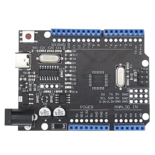
Arduino is an open-source electronics platform based on easy-to-use hardware and software. It consists of a microcontroller and a development environment for writing code to control various electronic components. Arduino boards are widely used for prototyping, educational purposes, and hobbyist projects due to their simplicity and versatility.
Explore Projects Built with ARDUINO
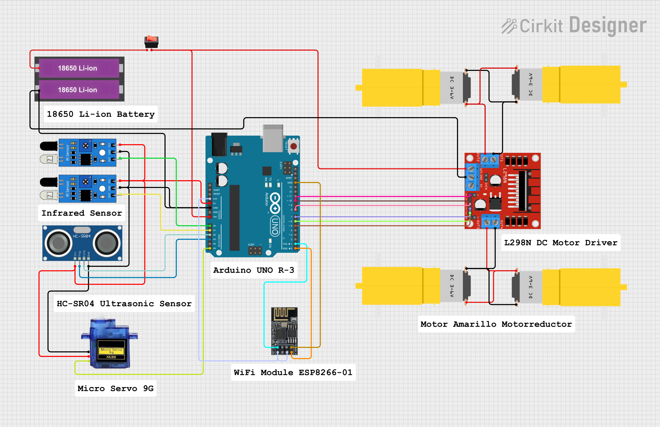
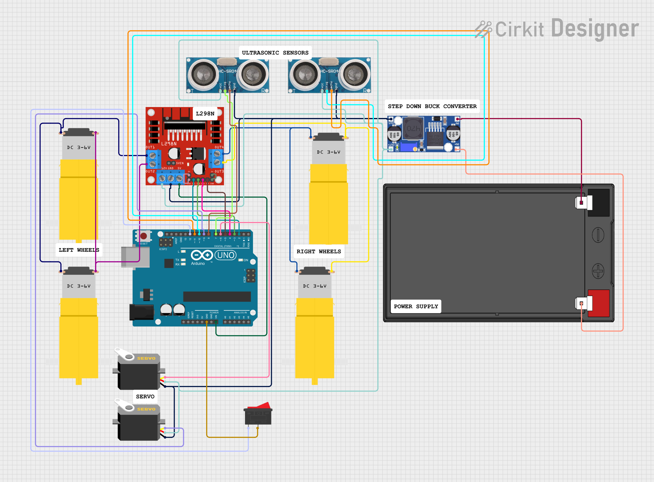
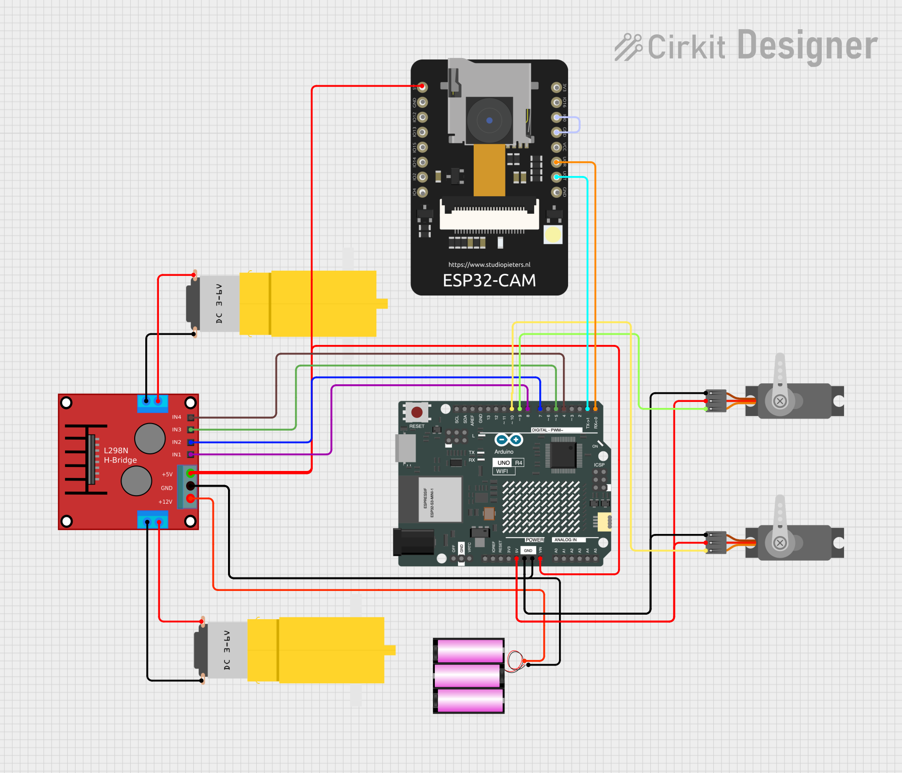
Explore Projects Built with ARDUINO
Common Applications and Use Cases
- Prototyping IoT (Internet of Things) devices
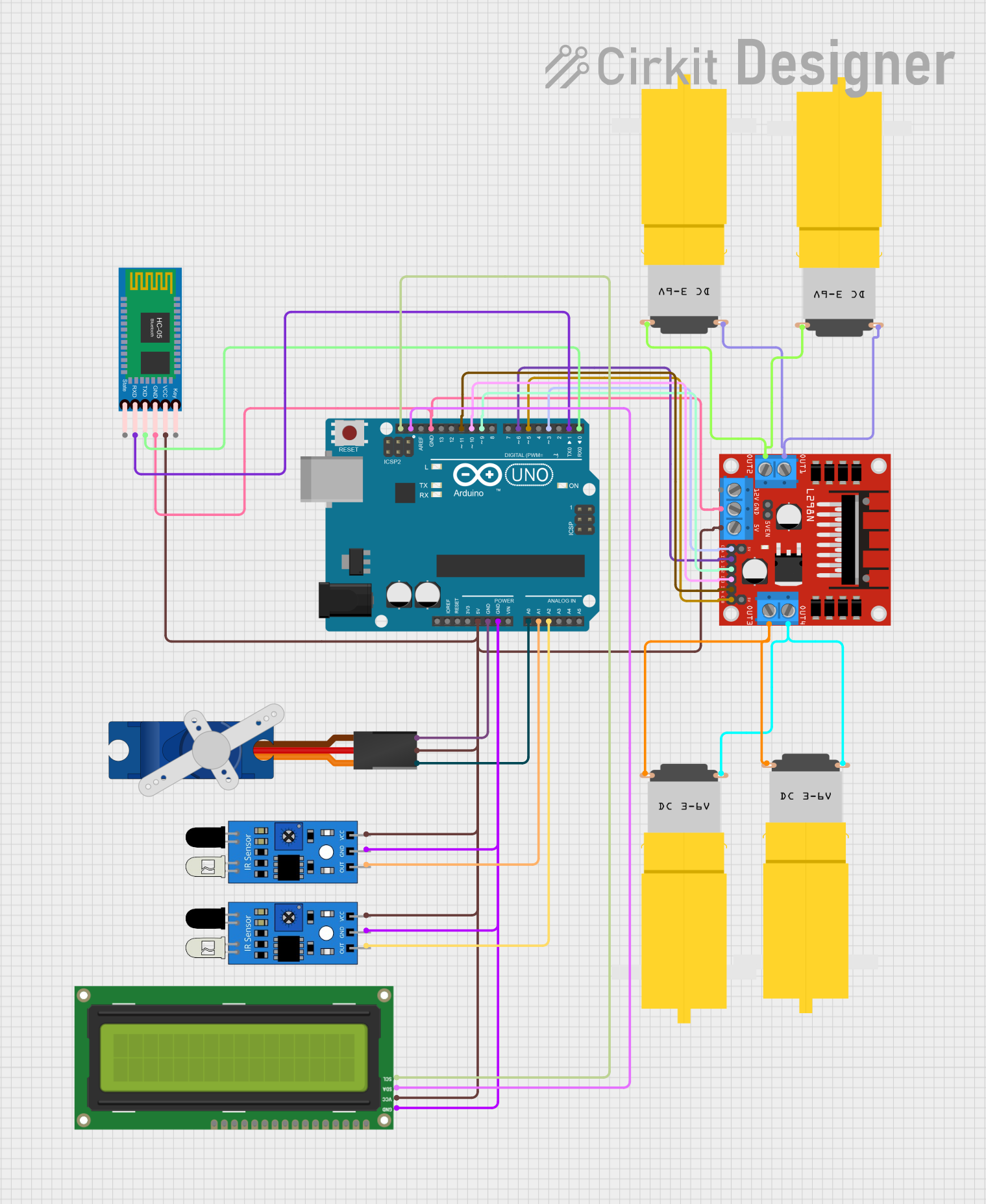
- Robotics and automation projects
- Sensor data acquisition and processing
- Home automation systems
- Educational tools for learning programming and electronics
- Wearable technology and interactive art installations
Technical Specifications
Arduino boards come in various models, such as the Arduino UNO, Mega, Nano, and others. Below are the general technical specifications for the Arduino UNO, one of the most popular models:
Key Technical Details
| Specification | Value |
|---|---|
| Microcontroller | ATmega328P |
| Operating Voltage | 5V |
| Input Voltage (limit) | 6-20V |
| Digital I/O Pins | 14 (6 PWM outputs) |
| Analog Input Pins | 6 |
| DC Current per I/O Pin | 20 mA |
| Flash Memory | 32 KB (0.5 KB used by bootloader) |
| SRAM | 2 KB |
| EEPROM | 1 KB |
| Clock Speed | 16 MHz |
| Communication | UART, I2C, SPI |
Pin Configuration and Descriptions
| Pin Name | Description |
|---|---|
| Digital Pins | Pins 0-13: Used for digital input/output. Pins 3, 5, 6, 9, 10, and 11 support PWM. |
| Analog Pins | Pins A0-A5: Used for analog input (0-1023 resolution). |
| Power Pins | VIN, 5V, 3.3V, GND: Provide power to the board or connected components. |
| Reset Pin | Resets the microcontroller when triggered. |
| TX/RX | Pins 0 (RX) and 1 (TX): Used for serial communication. |
Usage Instructions
How to Use the Arduino in a Circuit
- Power the Arduino: Connect the Arduino to a power source using a USB cable or an external power supply (6-12V).
- Connect Components: Attach sensors, actuators, or other components to the appropriate pins.
- Write Code: Use the Arduino IDE to write a program (sketch) in C/C++.
- Upload Code: Connect the Arduino to your computer via USB and upload the code using the IDE.
- Run the Circuit: Once the code is uploaded, the Arduino will execute the program and interact with the connected components.
Important Considerations and Best Practices
- Voltage Levels: Ensure that the input voltage does not exceed the specified limits (6-20V).
- Pin Current Limits: Avoid drawing more than 20 mA per I/O pin to prevent damage.
- Use Pull-up/Pull-down Resistors: For stable digital input readings, use pull-up or pull-down resistors as needed.
- Debugging: Use the Serial Monitor in the Arduino IDE to debug your code and monitor data.
- Static Electricity: Handle the board carefully to avoid damage from static discharge.
Example Code: Blinking an LED
Below is an example of how to blink an LED connected to pin 13 of the Arduino UNO:
// This program blinks an LED connected to pin 13 of the Arduino UNO.
// The LED will turn on for 1 second and off for 1 second in a loop.

void setup() {
  pinMode(13, OUTPUT); // Set pin 13 as an output pin
}

void loop() {
  digitalWrite(13, HIGH); // Turn the LED on
  delay(1000);            // Wait for 1 second
  digitalWrite(13, LOW);  // Turn the LED off
  delay(1000);            // Wait for 1 second
}
Troubleshooting and FAQs
Common Issues and Solutions
Arduino Not Detected by Computer
- Ensure the USB cable is properly connected.
- Check if the correct COM port is selected in the Arduino IDE.
- Install or update the necessary USB drivers.
Code Upload Fails
- Verify that the correct board and port are selected in the Arduino IDE.
- Press the reset button on the Arduino before uploading the code.
- Ensure no other program is using the COM port.
Components Not Working as Expected
- Double-check the wiring and connections.
- Verify that the code logic matches the circuit design.
- Use a multimeter to test for power and signal continuity.
Arduino Overheating
- Ensure the input voltage is within the specified range.
- Avoid drawing excessive current from the pins.
FAQs
Q: Can I power the Arduino with a battery?
A: Yes, you can power the Arduino using a 9V battery connected to the VIN and GND pins or the DC power jack.
Q: Can I use the Arduino to control high-power devices?
A: Yes, but you will need external components like relays, transistors, or motor drivers to handle high-power devices safely.
Q: How do I reset the Arduino?
A: Press the reset button on the board, or connect the RESET pin to GND momentarily.
Q: Can I use multiple sensors with the Arduino?
A: Yes, you can connect multiple sensors as long as you have enough pins and power available. Use multiplexers or I2C/SPI communication for more complex setups.