How to Use C13 Inlet Module Plug Power Socket: Examples, Pinouts, and Specs
Introduction
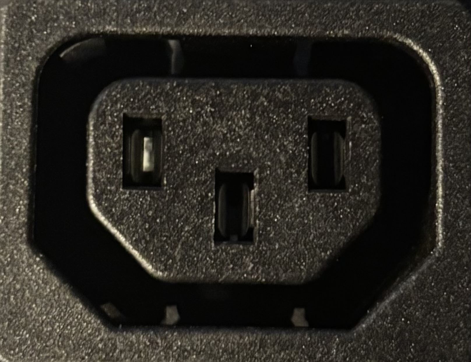
The C13 inlet module is a standardized power socket commonly used in electrical devices to facilitate the connection of power cords. It is designed to be compatible with C14 plugs, ensuring a secure and reliable power connection. This component is widely used in applications such as computer power supplies, server racks, medical equipment, and other electronic devices requiring a detachable power connection.
Explore Projects Built with C13 Inlet Module Plug Power Socket


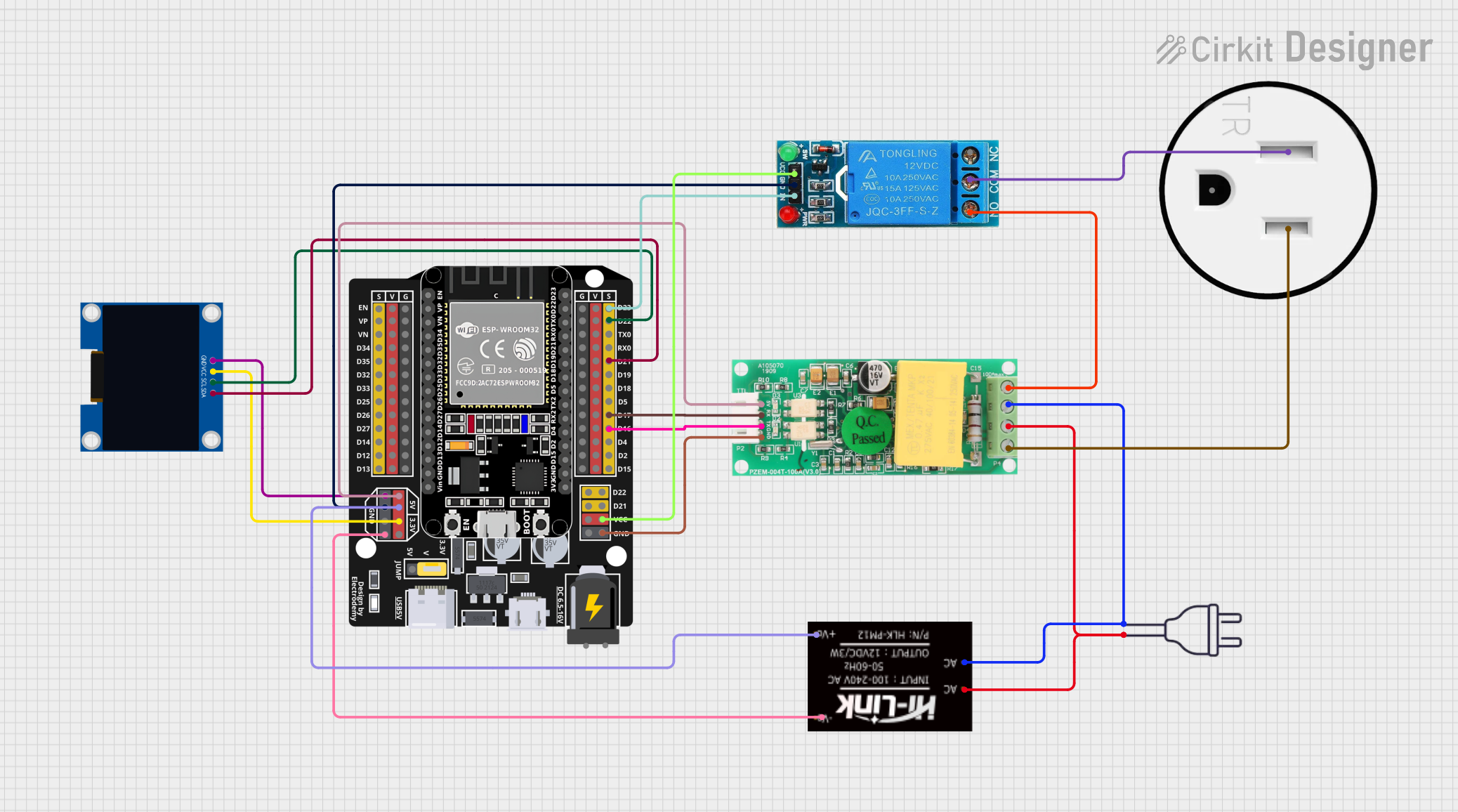
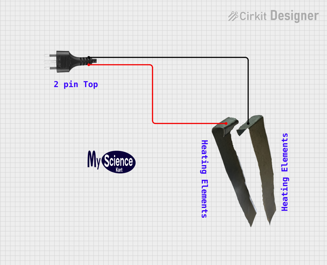
Explore Projects Built with C13 Inlet Module Plug Power Socket
Common Applications and Use Cases
- Desktop computers and power supplies
- Server racks and data center equipment
- Audio and video equipment
- Medical devices
- Industrial machinery
- Test and measurement instruments
Technical Specifications
The C13 inlet module adheres to international standards, ensuring compatibility and safety in a wide range of applications. Below are the key technical details and pin configuration.
Key Technical Details
| Parameter | Specification |
|---|---|
| Rated Voltage | 250V AC |
| Rated Current | 10A (varies by model and region) |
| Operating Frequency | 50/60 Hz |
| Connector Compatibility | IEC 60320 C14 plug |
| Mounting Style | Panel mount or snap-in |
| Material | High-temperature thermoplastic |
| Safety Standards | UL, CSA, VDE, and other certifications |
Pin Configuration and Descriptions
The C13 inlet module has three pins, which are typically arranged in a triangular configuration. Below is the pinout description:
| Pin Number | Name | Description |
|---|---|---|
| 1 | Line (L) | Live wire carrying the AC voltage |
| 2 | Neutral (N) | Neutral wire completing the circuit |
| 3 | Earth (E) | Ground connection for safety |
Usage Instructions
The C13 inlet module is straightforward to use and integrate into electronic devices. Follow the steps and considerations below to ensure proper installation and operation.
How to Use the Component in a Circuit
Mounting the Module:
- Secure the C13 inlet module to the device's panel using screws or snap-in clips, depending on the mounting style.
- Ensure the module is firmly attached to prevent movement during operation.
Wiring the Pins:
- Connect the Line (L) pin to the live wire of the AC power source.
- Connect the Neutral (N) pin to the neutral wire of the AC power source.
- Connect the Earth (E) pin to the ground wire for safety.
- Use insulated crimp terminals or solder connections to ensure a secure and reliable connection.
Testing the Connection:
- After wiring, test the connections with a multimeter to verify continuity and proper wiring.
- Ensure there are no short circuits or loose connections.
Connecting the Power Cord:
- Insert a compatible C14 plug into the C13 inlet module.
- Ensure the plug fits securely to avoid accidental disconnection.
Important Considerations and Best Practices
- Safety First: Always disconnect the power source before wiring or handling the C13 inlet module.
- Wire Gauge: Use appropriate wire gauges that can handle the rated current (e.g., 18 AWG for 10A applications).
- Grounding: Ensure the Earth (E) pin is properly connected to the device's chassis or ground for safety.
- Certifications: Use C13 inlet modules that comply with safety standards (e.g., UL, VDE) for reliable operation.
- Heat Dissipation: Avoid placing the module near heat-sensitive components to prevent overheating.
Troubleshooting and FAQs
Common Issues and Solutions
| Issue | Possible Cause | Solution |
|---|---|---|
| No power to the device | Loose or incorrect wiring | Verify wiring and ensure secure connections. |
| Overheating of the module | Exceeding current rating or poor ventilation | Reduce load or improve ventilation. |
| Plug does not fit securely | Incompatible or damaged plug | Use a compatible C14 plug or replace the damaged plug. |
| Electrical noise or interference | Poor grounding or loose connections | Ensure proper grounding and tighten all connections. |
FAQs
Can the C13 inlet module handle 110V AC?
Yes, the C13 inlet module is designed to handle a wide range of voltages, including 110V and 250V AC, as long as the current rating is not exceeded.Is the C13 inlet module waterproof?
Standard C13 inlet modules are not waterproof. For outdoor or wet environments, use a weatherproof enclosure.What is the difference between C13 and C14 connectors?
The C13 is the socket (inlet) that connects to a C14 plug. The C14 plug is typically found on power cords.Can I use the C13 inlet module with DC power?
No, the C13 inlet module is designed for AC power applications only.
By following this documentation, users can safely and effectively integrate the C13 inlet module into their electronic devices.