How to Use Signal Amplifier: Examples, Pinouts, and Specs
Introduction
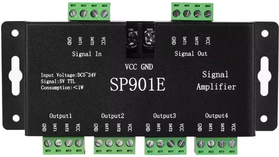
The SP901E Signal Amplifier is a versatile electronic component designed to increase the amplitude of input signals. By amplifying weak signals, it ensures stronger transmission and improved signal quality in various electronic circuits. This component is widely used in audio systems, communication devices, and sensor signal processing applications.
Explore Projects Built with Signal Amplifier
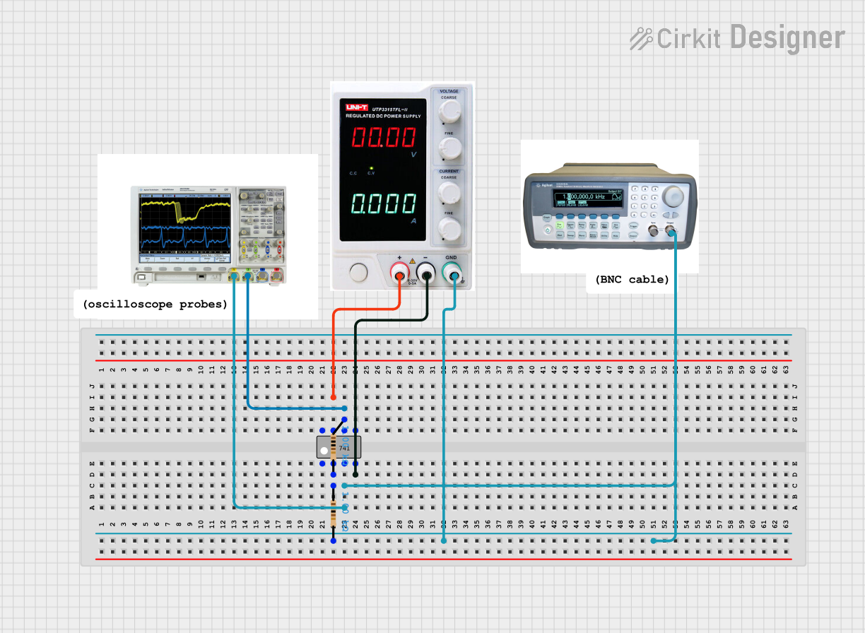

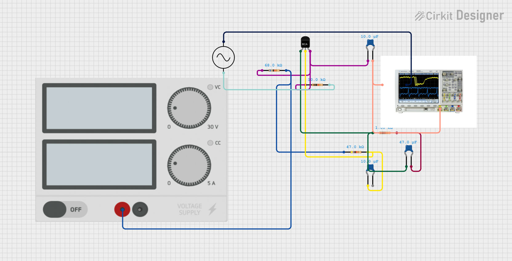
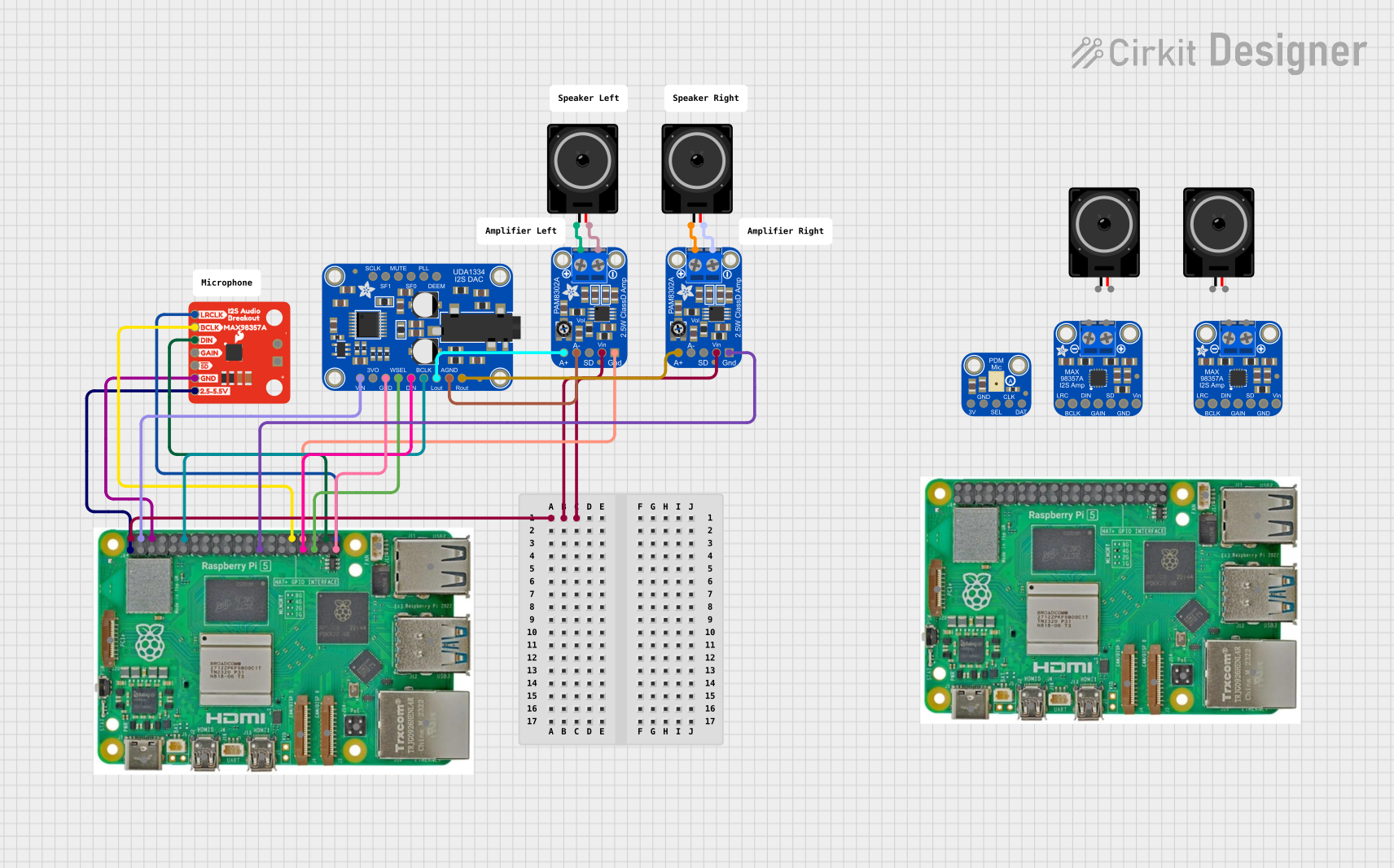
Explore Projects Built with Signal Amplifier
Common Applications and Use Cases
- Audio Systems: Amplifying audio signals for speakers or headphones.
- Communication Devices: Boosting RF or analog signals for better transmission.
- Sensor Circuits: Enhancing weak sensor outputs for further processing.
- Test and Measurement Equipment: Amplifying signals for accurate readings.
Technical Specifications
The SP901E Signal Amplifier is designed for high performance and reliability. Below are its key technical details:
Key Technical Details
| Parameter | Value |
|---|---|
| Manufacturer | SP901E |
| Part ID | SP901E |
| Supply Voltage (Vcc) | 3.3V to 12V |
| Input Signal Range | 0.1V to 2V (peak-to-peak) |
| Gain | Adjustable (10x to 100x) |
| Output Signal Range | 0.1V to 10V (peak-to-peak) |
| Bandwidth | 20 Hz to 20 kHz |
| Input Impedance | 10 kΩ |
| Output Impedance | 50 Ω |
| Power Consumption | < 50 mW |
| Operating Temperature | -40°C to +85°C |
| Package Type | DIP-8 or SMD |
Pin Configuration and Descriptions
The SP901E Signal Amplifier is available in an 8-pin package. Below is the pinout and description:
| Pin Number | Pin Name | Description |
|---|---|---|
| 1 | Vcc | Positive power supply (3.3V to 12V). |
| 2 | GND | Ground connection. |
| 3 | IN+ | Non-inverting input for the signal. |
| 4 | IN- | Inverting input for the signal. |
| 5 | GAIN | Gain adjustment pin (connect resistor to GND). |
| 6 | OUT | Amplified signal output. |
| 7 | NC | No connection (leave unconnected). |
| 8 | ENABLE | Enable/disable the amplifier (active high). |
Usage Instructions
The SP901E Signal Amplifier is easy to integrate into a variety of circuits. Follow the steps below to use it effectively:
How to Use the Component in a Circuit
- Power Supply: Connect the Vcc pin to a stable power source (3.3V to 12V) and the GND pin to the ground.
- Input Signal: Feed the input signal to the IN+ pin. If differential input is required, connect the complementary signal to the IN- pin.
- Gain Adjustment: Use a resistor between the GAIN pin and GND to set the desired gain. For example:
- 10 kΩ resistor for 10x gain.
- 1 kΩ resistor for 100x gain.
- Output Signal: The amplified signal will be available at the OUT pin. Connect this to the next stage of your circuit.
- Enable/Disable: Use the ENABLE pin to control the amplifier. Pull it high to enable the amplifier or low to disable it.
Important Considerations and Best Practices
- Power Supply Decoupling: Use a 0.1 µF capacitor close to the Vcc pin to reduce noise.
- Input Signal Range: Ensure the input signal does not exceed the specified range (0.1V to 2V peak-to-peak).
- Thermal Management: Operate the amplifier within the specified temperature range to avoid overheating.
- Output Load: Connect the output to a load with impedance greater than 50 Ω for optimal performance.
Example: Connecting SP901E to an Arduino UNO
The SP901E can be used with an Arduino UNO to amplify sensor signals. Below is an example circuit and code:
Circuit Diagram
- Connect the SP901E's Vcc pin to the Arduino's 5V pin and GND to the Arduino's GND.
- Connect the sensor output to the IN+ pin of the SP901E.
- Connect a 10 kΩ resistor between the GAIN pin and GND for 10x gain.
- Connect the OUT pin of the SP901E to an analog input pin (e.g., A0) on the Arduino.
Arduino Code
// Example code to read amplified signal from SP901E and display it on Serial Monitor

const int analogPin = A0; // Pin connected to SP901E OUT pin
int sensorValue = 0;      // Variable to store the analog reading

void setup() {
  Serial.begin(9600); // Initialize Serial communication at 9600 baud
}

void loop() {
  sensorValue = analogRead(analogPin); // Read the amplified signal
  float voltage = sensorValue * (5.0 / 1023.0); // Convert to voltage
  Serial.print("Amplified Signal Voltage: ");
  Serial.println(voltage); // Print the voltage to Serial Monitor
  delay(500); // Wait for 500ms before the next reading
}
Troubleshooting and FAQs
Common Issues and Solutions
| Issue | Possible Cause | Solution |
|---|---|---|
| No output signal | Amplifier not enabled | Ensure ENABLE pin is pulled high. |
| Distorted output signal | Input signal exceeds range | Reduce input signal amplitude. |
| Noisy output | Insufficient power supply decoupling | Add a 0.1 µF capacitor near the Vcc pin. |
| Incorrect gain | Wrong resistor value on GAIN pin | Use the correct resistor for desired gain. |
FAQs
Can I use the SP901E with a 3.3V power supply?
- Yes, the SP901E operates with a supply voltage as low as 3.3V.
What is the maximum output signal amplitude?
- The maximum output signal amplitude is 10V peak-to-peak, depending on the supply voltage.
Can I leave the IN- pin unconnected?
- Yes, if you are using the amplifier in single-ended mode, you can leave the IN- pin unconnected.
How do I disable the amplifier?
- Pull the ENABLE pin low to disable the amplifier.
By following this documentation, you can effectively integrate the SP901E Signal Amplifier into your projects and achieve optimal performance.