Introduction
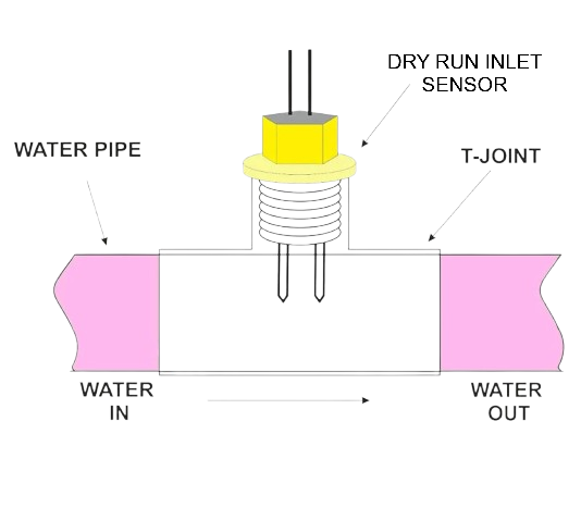
The DRY RUN INLET SENSOR by R.M ENTERPRISE (Part ID: SENSOR) is a specialized electronic component designed to detect the absence of water flow in a system. This sensor plays a critical role in protecting pumps and other water-dependent equipment from damage caused by dry running. By monitoring water flow, it ensures operational safety and enhances the longevity of the system.
Common Applications and Use Cases
- Protection of water pumps in residential, industrial, and agricultural systems.
- Monitoring water flow in HVAC systems.
- Ensuring operational safety in irrigation systems.
- Preventing damage to equipment in water filtration and purification systems.
Technical Specifications
The following table outlines the key technical details of the DRY RUN INLET SENSOR:
Pin Configuration and Descriptions
The DRY RUN INLET SENSOR has a 3-pin interface. The pin configuration is as follows:
Usage Instructions
How to Use the Component in a Circuit
- Power Supply: Connect the VCC pin to a DC power source (5V to 24V) and the GND pin to the ground of the circuit.
- Output Signal: Connect the OUT pin to a microcontroller or monitoring system to read the sensor's output signal.
- Placement: Install the sensor in the water inlet line of the system. Ensure that the sensor is securely mounted and aligned with the flow direction.
- Signal Interpretation:
- A High signal on the OUT pin indicates water flow is present.
- A Low signal on the OUT pin indicates no water flow (dry run condition).
Important Considerations and Best Practices
- Ensure the sensor is installed in a clean and debris-free section of the water line to avoid false readings.
- Avoid exposing the sensor to temperatures or pressures beyond its specified operating range.
- Use appropriate pull-up or pull-down resistors on the OUT pin if required by your microcontroller.
- Regularly inspect the sensor for blockages or damage to maintain accuracy.
Example: Connecting to an Arduino UNO
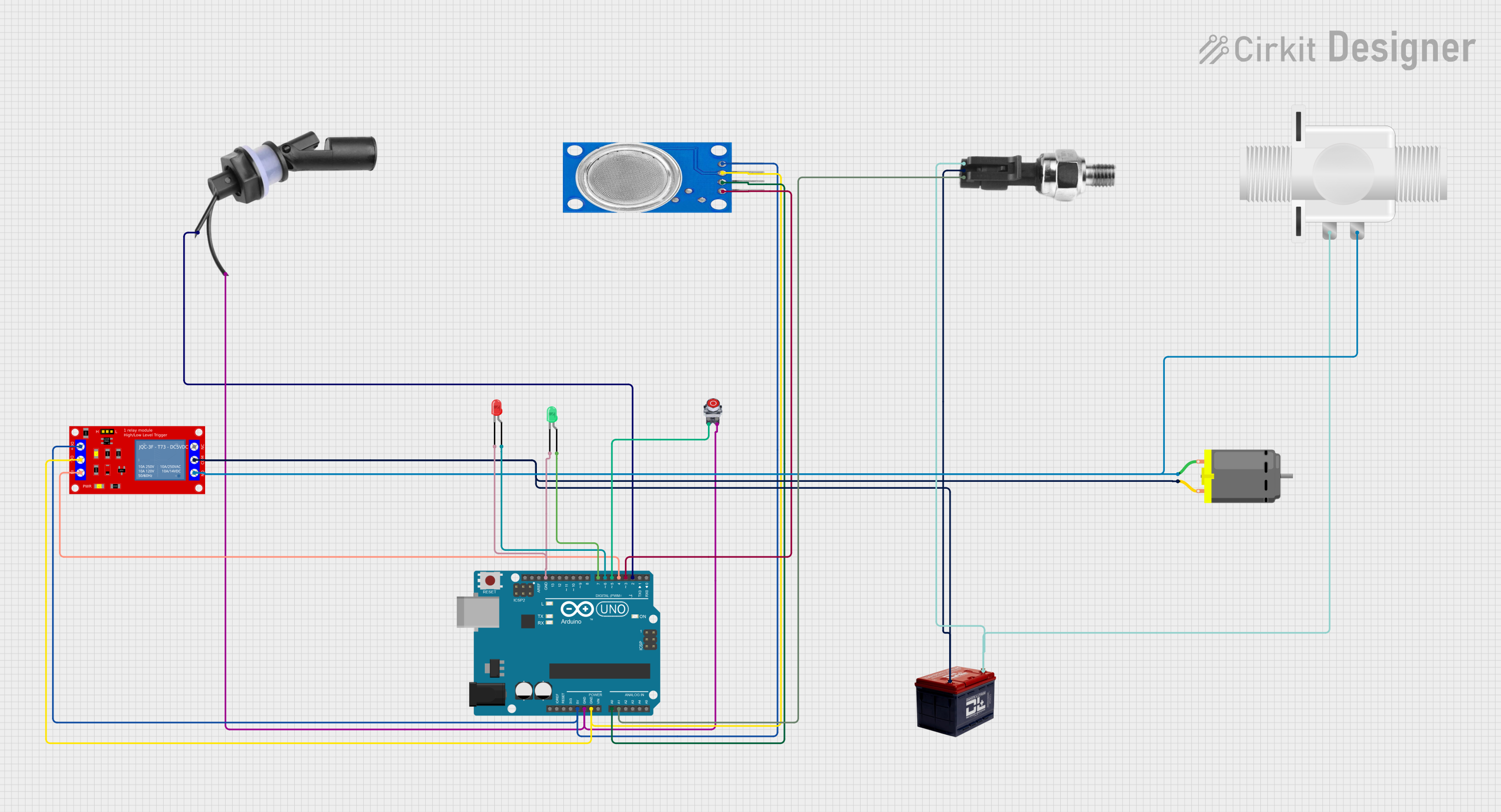
Below is an example of how to connect and use the DRY RUN INLET SENSOR with an Arduino UNO:
Circuit Connections
- VCC: Connect to the Arduino's 5V pin.
- GND: Connect to the Arduino's GND pin.
- OUT: Connect to digital pin 2 on the Arduino.
Arduino Code
// DRY RUN INLET SENSOR Example Code
// This code reads the sensor's output and prints the status to the Serial Monitor.

const int sensorPin = 2; // OUT pin of the sensor connected to digital pin 2
int sensorState = 0;     // Variable to store the sensor's state

void setup() {
  pinMode(sensorPin, INPUT); // Set sensor pin as input
  Serial.begin(9600);        // Initialize serial communication
}

void loop() {
  sensorState = digitalRead(sensorPin); // Read the sensor's output

  if (sensorState == HIGH) {
    // Water flow detected
    Serial.println("Water flow detected.");
  } else {
    // No water flow (dry run condition)
    Serial.println("No water flow detected! Check the system.");
  }

  delay(500); // Wait for 500ms before the next reading
}
Troubleshooting and FAQs
Common Issues Users Might Face
No Output Signal:
- Cause: Incorrect wiring or insufficient power supply.
- Solution: Verify the connections and ensure the power supply voltage is within the specified range.
False Dry Run Detection:
- Cause: Debris or air bubbles in the water line.
- Solution: Clean the water line and ensure proper installation of the sensor.
Intermittent Output:
- Cause: Loose connections or fluctuating power supply.
- Solution: Check all connections and use a stable power source.
Sensor Overheating:
- Cause: Operating the sensor beyond its temperature range.
- Solution: Ensure the sensor is used within the specified temperature range (-10°C to 60°C).
FAQs
Q1: Can the sensor detect partial water flow?
A1: No, the sensor is designed to detect the presence or absence of water flow, not the flow rate.
Q2: Is the sensor waterproof?
A2: Yes, the sensor housing is made of ABS plastic and is water-resistant, but it should not be submerged.
Q3: Can the sensor be used with AC-powered systems?
A3: The sensor operates on DC power only. Use a DC power supply or a rectifier circuit for AC systems.
Q4: What is the maximum cable length for the sensor?
A4: The maximum cable length depends on the operating voltage and signal integrity. For best results, keep the cable length under 2 meters.
By following this documentation, users can effectively integrate the DRY RUN INLET SENSOR into their systems and ensure reliable operation.

 Open Project in Cirkit Designer