How to Use Electromagnet: Examples, Pinouts, and Specs

Introduction
An electromagnet is a type of magnet in which the magnetic field is generated by an electric current. Manufactured by Uxcell, this component consists of a coil of wire wound around a ferromagnetic core, which amplifies the magnetic field when current flows through the coil. Electromagnets are widely used in applications where a controllable magnetic field is required.
Explore Projects Built with Electromagnet

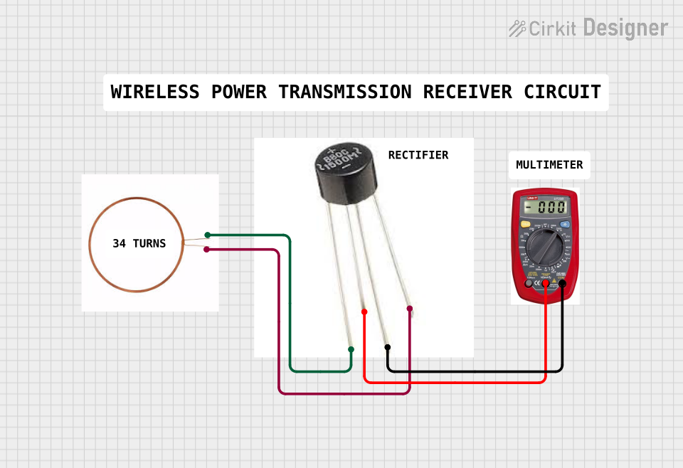

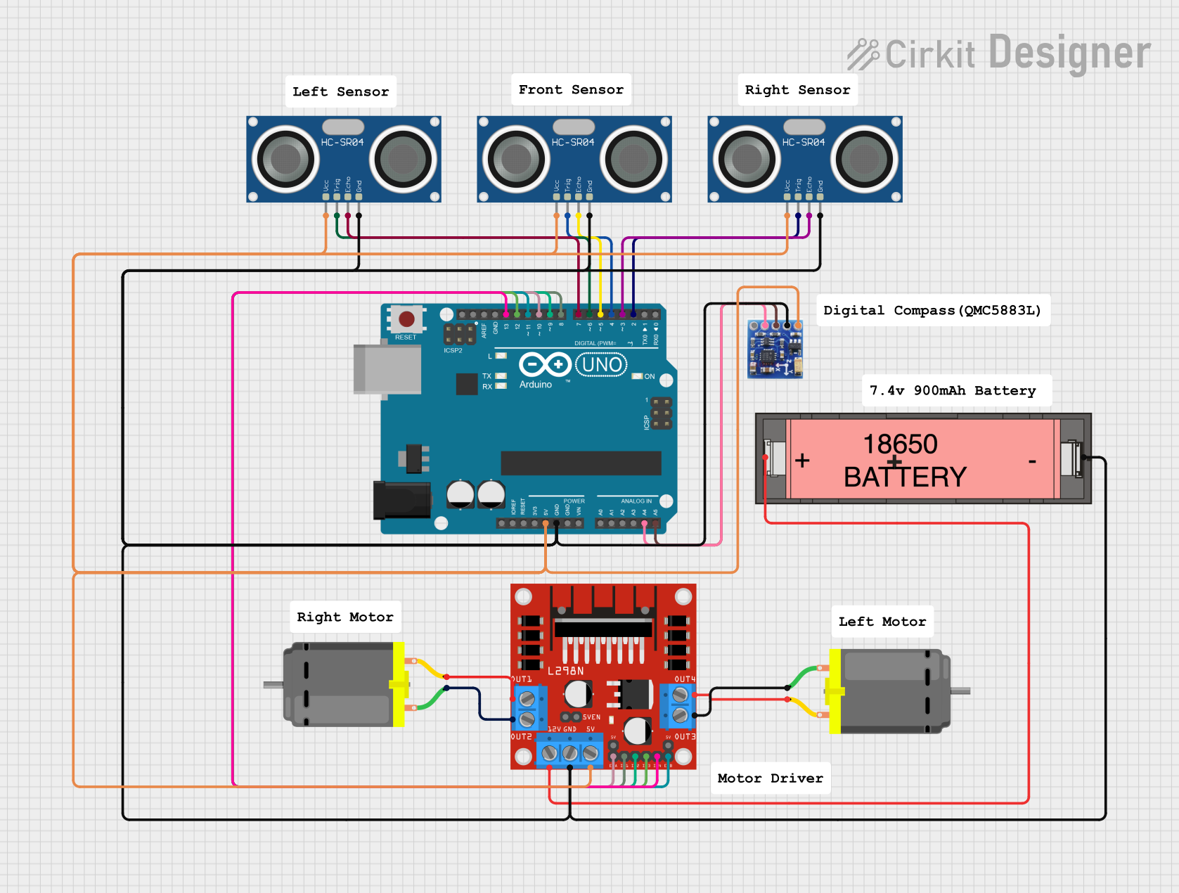
Explore Projects Built with Electromagnet
Common Applications and Use Cases
- Relays and Switches: Used in electromagnetic relays to control circuits.
- Motors and Generators: Essential in electric motors and generators for creating rotational motion.
- Magnetic Lifting Devices: Used in cranes to lift heavy ferromagnetic materials.
- Magnetic Locks: Found in security systems for doors and safes.
- Particle Accelerators: Used to guide charged particles in scientific research.
Technical Specifications
Below are the key technical details for the Uxcell Electromagnet:
| Parameter | Value |
|---|---|
| Operating Voltage | 12V DC |
| Current Consumption | 0.5A |
| Power Rating | 6W |
| Magnetic Force | 10N (approx.) |
| Coil Resistance | 24Ω |
| Core Material | Ferromagnetic (Iron or Steel) |
| Wire Material | Copper |
| Dimensions | 20mm (diameter) x 30mm (length) |
| Weight | 50g |
Pin Configuration and Descriptions
The Uxcell Electromagnet has two terminals for electrical connections:
| Pin | Description |
|---|---|
| Pin 1 | Positive terminal (+12V DC input) |
| Pin 2 | Negative terminal (Ground) |
Usage Instructions
How to Use the Electromagnet in a Circuit
- Power Supply: Connect the positive terminal (Pin 1) to a 12V DC power source and the negative terminal (Pin 2) to ground.
- Control Circuit: Use a switch, relay, or transistor to control the current flow through the electromagnet.
- Load Considerations: Ensure the power supply can provide at least 0.5A of current to avoid underpowering the electromagnet.
- Heat Management: Prolonged use may cause the coil to heat up. Allow cooling periods to prevent overheating.
Important Considerations and Best Practices
- Polarity: Always connect the terminals with the correct polarity to avoid damage.
- Current Limiting: Use a current-limiting resistor or a regulated power supply to prevent excessive current.
- Mounting: Secure the electromagnet firmly to avoid movement during operation.
- Magnetic Interference: Keep sensitive electronic components away from the electromagnet to avoid interference.
- Arduino Integration: The electromagnet can be controlled using an Arduino UNO with a transistor or relay module.
Example Arduino Code
Below is an example of how to control the Uxcell Electromagnet using an Arduino UNO and an NPN transistor (e.g., 2N2222):
// Define the pin connected to the transistor's base
const int electromagnetPin = 9;

void setup() {
  pinMode(electromagnetPin, OUTPUT); // Set the pin as an output
}

void loop() {
  digitalWrite(electromagnetPin, HIGH); // Turn on the electromagnet
  delay(1000); // Keep it on for 1 second
  digitalWrite(electromagnetPin, LOW);  // Turn off the electromagnet
  delay(1000); // Keep it off for 1 second
}
Circuit Notes:
- Connect the Arduino's digital pin 9 to the base of the NPN transistor through a 1kΩ resistor.
- Connect the electromagnet's positive terminal to the 12V power supply.
- Connect the electromagnet's negative terminal to the transistor's collector.
- Connect the transistor's emitter to ground.
Troubleshooting and FAQs
Common Issues and Solutions
Electromagnet Not Activating:
- Cause: Insufficient power supply or incorrect wiring.
- Solution: Verify the power supply voltage and current. Check the wiring for proper connections.
Overheating:
- Cause: Prolonged operation or excessive current.
- Solution: Use the electromagnet intermittently and ensure the current does not exceed 0.5A.
Weak Magnetic Field:
- Cause: Low input voltage or damaged coil.
- Solution: Ensure the input voltage is 12V. Check the coil resistance with a multimeter.
Interference with Other Devices:
- Cause: Magnetic field affecting nearby components.
- Solution: Increase the distance between the electromagnet and sensitive devices.
FAQs
Q1: Can I use a higher voltage to increase the magnetic force?
A1: No, exceeding the rated 12V may damage the coil or cause overheating. Use only the specified voltage.
Q2: How do I know if the electromagnet is working?
A2: Place a small ferromagnetic object (e.g., a nail) near the electromagnet. If it attracts the object when powered, it is functioning.
Q3: Can I use this electromagnet with a battery?
A3: Yes, as long as the battery provides 12V DC and can supply at least 0.5A of current.
Q4: Is the electromagnet waterproof?
A4: No, the Uxcell Electromagnet is not waterproof. Avoid exposing it to moisture or liquids.
By following this documentation, you can effectively integrate and troubleshoot the Uxcell Electromagnet in your projects.