Cirkit Designer Logo
Cirkit Designer
Your all-in-one circuit design IDE
Home / 
Component Documentation

How to Use Step-down 12 To 5V 3A LM2596 : Examples, Pinouts, and Specs

Image of Step-down 12 To 5V 3A LM2596
Cirkit Designer LogoDesign with Step-down 12 To 5V 3A LM2596 in Cirkit Designer

Introduction

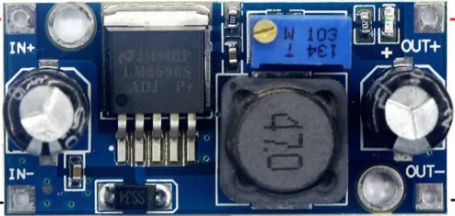
The Step-down 12 To 5V 3A LM2596 is a DC-DC buck converter designed to efficiently step down a 12V input voltage to a stable 5V output. It is capable of delivering a maximum output current of 3A, making it ideal for powering devices that require a lower voltage, such as microcontrollers, sensors, and USB-powered devices. This module is widely used in embedded systems, robotics, and portable electronics due to its compact size, high efficiency, and ease of use.

Explore Projects Built with Step-down 12 To 5V 3A LM2596

Use Cirkit Designer to design, explore, and prototype these projects online. Some projects support real-time simulation. Click "Open Project" to start designing instantly!
Voltage Regulation System with MT3608 Boost and LM2596 Buck Converters
Image of solar system router ups: A project utilizing Step-down 12 To 5V 3A LM2596  in a practical application
This circuit consists of two MT3608 boost converters and an LM2596 step-down module, each connected to separate 12V power supplies. The MT3608 modules are configured to step up the voltage from their respective power supplies, while the LM2596 module steps down the voltage from a 12V battery. Diodes are used to ensure correct current flow direction, potentially for protection or isolation between different parts of the circuit.
Cirkit Designer LogoOpen Project in Cirkit Designer
12V to 5V Power Supply with LED Indicator and Push Switch
Image of Power Supply LVCO: A project utilizing Step-down 12 To 5V 3A LM2596  in a practical application
This circuit is a 12V to 5V regulated power supply with an LED indicator. It uses a 5408 diode for reverse polarity protection, an LM340T5 7805 voltage regulator to step down the voltage to 5V, and a push switch to control the LED indicator. The circuit also includes capacitors for filtering and a resistor to limit the current through the LED.
Cirkit Designer LogoOpen Project in Cirkit Designer
USB Power Supply with Overcurrent Protection
Image of USB Charging port: A project utilizing Step-down 12 To 5V 3A LM2596  in a practical application
This circuit is designed to step down voltage from a 12V battery to a lower voltage suitable for USB devices. It includes a buck converter connected to the battery through a fuse and fuse holder for overcurrent protection. The output of the buck converter is connected to a USB female port, providing a regulated power supply for USB-powered devices.
Cirkit Designer LogoOpen Project in Cirkit Designer
Battery-Powered DC-DC Converter System for Multi-Voltage Power Distribution
Image of test 1 ih: A project utilizing Step-down 12 To 5V 3A LM2596  in a practical application
This circuit converts a 38.5V battery output to multiple lower voltage levels using a series of DC-DC converters and a power module. It includes an emergency stop switch for safety and distributes power to various components such as a relay module, USB ports, and a bus servo adaptor.
Cirkit Designer LogoOpen Project in Cirkit Designer

Explore Projects Built with Step-down 12 To 5V 3A LM2596

Use Cirkit Designer to design, explore, and prototype these projects online. Some projects support real-time simulation. Click "Open Project" to start designing instantly!
Image of solar system router ups: A project utilizing Step-down 12 To 5V 3A LM2596  in a practical application
Voltage Regulation System with MT3608 Boost and LM2596 Buck Converters
This circuit consists of two MT3608 boost converters and an LM2596 step-down module, each connected to separate 12V power supplies. The MT3608 modules are configured to step up the voltage from their respective power supplies, while the LM2596 module steps down the voltage from a 12V battery. Diodes are used to ensure correct current flow direction, potentially for protection or isolation between different parts of the circuit.
Cirkit Designer LogoOpen Project in Cirkit Designer
Image of Power Supply LVCO: A project utilizing Step-down 12 To 5V 3A LM2596  in a practical application
12V to 5V Power Supply with LED Indicator and Push Switch
This circuit is a 12V to 5V regulated power supply with an LED indicator. It uses a 5408 diode for reverse polarity protection, an LM340T5 7805 voltage regulator to step down the voltage to 5V, and a push switch to control the LED indicator. The circuit also includes capacitors for filtering and a resistor to limit the current through the LED.
Cirkit Designer LogoOpen Project in Cirkit Designer
Image of USB Charging port: A project utilizing Step-down 12 To 5V 3A LM2596  in a practical application
USB Power Supply with Overcurrent Protection
This circuit is designed to step down voltage from a 12V battery to a lower voltage suitable for USB devices. It includes a buck converter connected to the battery through a fuse and fuse holder for overcurrent protection. The output of the buck converter is connected to a USB female port, providing a regulated power supply for USB-powered devices.
Cirkit Designer LogoOpen Project in Cirkit Designer
Image of test 1 ih: A project utilizing Step-down 12 To 5V 3A LM2596  in a practical application
Battery-Powered DC-DC Converter System for Multi-Voltage Power Distribution
This circuit converts a 38.5V battery output to multiple lower voltage levels using a series of DC-DC converters and a power module. It includes an emergency stop switch for safety and distributes power to various components such as a relay module, USB ports, and a bus servo adaptor.
Cirkit Designer LogoOpen Project in Cirkit Designer

Common Applications

  • Powering microcontrollers like Arduino, Raspberry Pi, and ESP32
  • USB device power supplies
  • Battery-powered systems
  • Robotics and automation projects
  • LED lighting systems

Technical Specifications

The following table outlines the key technical details of the LM2596 step-down module:

Parameter Value
Input Voltage Range 7V to 40V
Output Voltage Adjustable (default: 5V)
Maximum Output Current 3A
Efficiency Up to 92%
Switching Frequency 150 kHz
Output Ripple < 30 mV
Operating Temperature -40°C to +85°C
Dimensions ~43mm x 21mm x 14mm

Pin Configuration and Descriptions

The LM2596 module typically has the following pin configuration:

Pin Name Description
VIN Input voltage pin (connect to 12V or other input voltage within the range)
GND Ground pin (common ground for input and output)
VOUT Output voltage pin (provides the stepped-down voltage, e.g., 5V)

Usage Instructions

How to Use the LM2596 in a Circuit

  1. Connect the Input Voltage:

    • Connect the VIN pin to a DC power source (e.g., 12V battery or adapter).
    • Ensure the input voltage is within the module's range (7V to 40V).
  2. Connect the Output Load:

    • Connect the VOUT pin to the device or circuit requiring 5V.
    • Ensure the load does not exceed the maximum output current of 3A.
  3. Adjust the Output Voltage (if needed):

    • Use the onboard potentiometer to adjust the output voltage.
    • Turn the potentiometer clockwise to increase the voltage and counterclockwise to decrease it.
    • Use a multimeter to measure the output voltage while adjusting.
  4. Power On:

    • Once all connections are secure, power on the input source.
    • Verify the output voltage and ensure the module is operating as expected.

Important Considerations and Best Practices

  • Heat Dissipation: At high currents, the module may generate heat. Use a heatsink or ensure proper ventilation to prevent overheating.
  • Input Voltage: Always ensure the input voltage is higher than the desired output voltage (minimum 2V difference).
  • Polarity: Double-check the polarity of the input and output connections to avoid damage.
  • Load Current: Do not exceed the maximum output current of 3A to prevent damage to the module.

Example: Using LM2596 with Arduino UNO

The LM2596 can be used to power an Arduino UNO by stepping down a 12V input to 5V. Below is an example circuit and code:

Circuit Connections

  • Connect the VIN pin of the LM2596 to a 12V DC power source.
  • Connect the GND pin of the LM2596 to the ground of the power source and Arduino.
  • Connect the VOUT pin of the LM2596 to the 5V pin of the Arduino UNO.

Example Code

// Example code to blink an LED using Arduino UNO powered by LM2596
// Ensure the LM2596 is providing a stable 5V output to the Arduino

const int ledPin = 13; // Built-in LED pin on Arduino UNO

void setup() {
  pinMode(ledPin, OUTPUT); // Set the LED pin as an output
}

void loop() {
  digitalWrite(ledPin, HIGH); // Turn the LED on
  delay(1000);                // Wait for 1 second
  digitalWrite(ledPin, LOW);  // Turn the LED off
  delay(1000);                // Wait for 1 second
}

Troubleshooting and FAQs

Common Issues and Solutions

  1. No Output Voltage:

    • Cause: Incorrect wiring or loose connections.
    • Solution: Verify all connections and ensure the input voltage is within the specified range.
  2. Output Voltage is Incorrect:

    • Cause: Potentiometer not adjusted correctly.
    • Solution: Use a multimeter to measure the output voltage and adjust the potentiometer as needed.
  3. Module Overheating:

    • Cause: Excessive load current or poor ventilation.
    • Solution: Reduce the load current or add a heatsink to the module.
  4. High Output Ripple:

    • Cause: Insufficient input or output capacitors.
    • Solution: Add additional capacitors (e.g., 100µF electrolytic) to the input and output terminals.

FAQs

Q: Can I use the LM2596 to power a Raspberry Pi?
A: Yes, but ensure the output voltage is set to 5V and the current requirement of the Raspberry Pi (including peripherals) does not exceed 3A.

Q: Is the output voltage adjustable?
A: Yes, the output voltage can be adjusted using the onboard potentiometer.

Q: Can I use the LM2596 with a 24V input?
A: Yes, as long as the input voltage is within the range of 7V to 40V and the output voltage is set appropriately.

Q: Does the module have reverse polarity protection?
A: No, the LM2596 module does not have built-in reverse polarity protection. Always double-check the polarity of your connections.