How to Use MKE-M01_LED: Examples, Pinouts, and Specs
Introduction
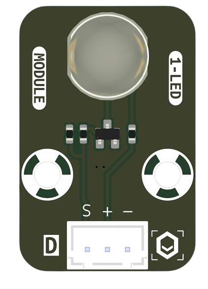
The MKE-M01_LED is a compact LED module manufactured by MakerEdu.vn (Part ID: LED). It is designed for low-power applications, offering bright illumination while consuming minimal energy. This module is ideal for projects requiring efficient and reliable lighting, such as indicator lights, decorative lighting, and educational electronics projects. Its small size and ease of use make it suitable for both beginners and experienced users.
Explore Projects Built with MKE-M01_LED

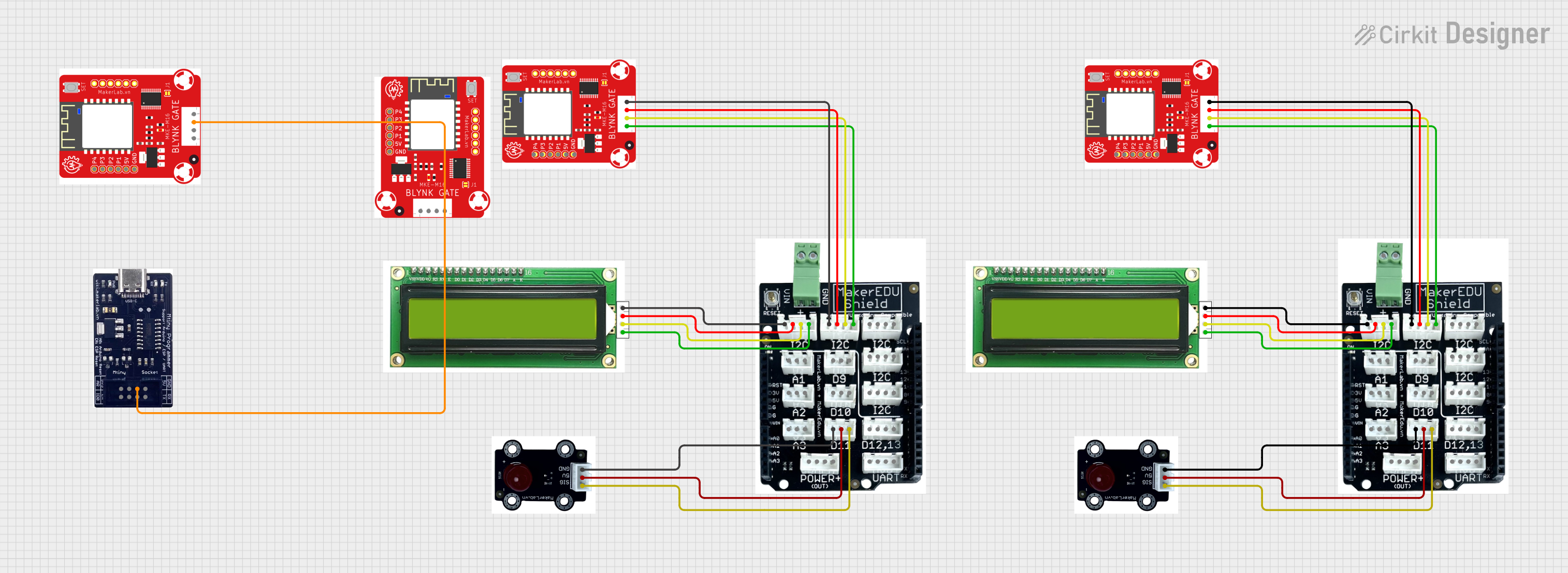
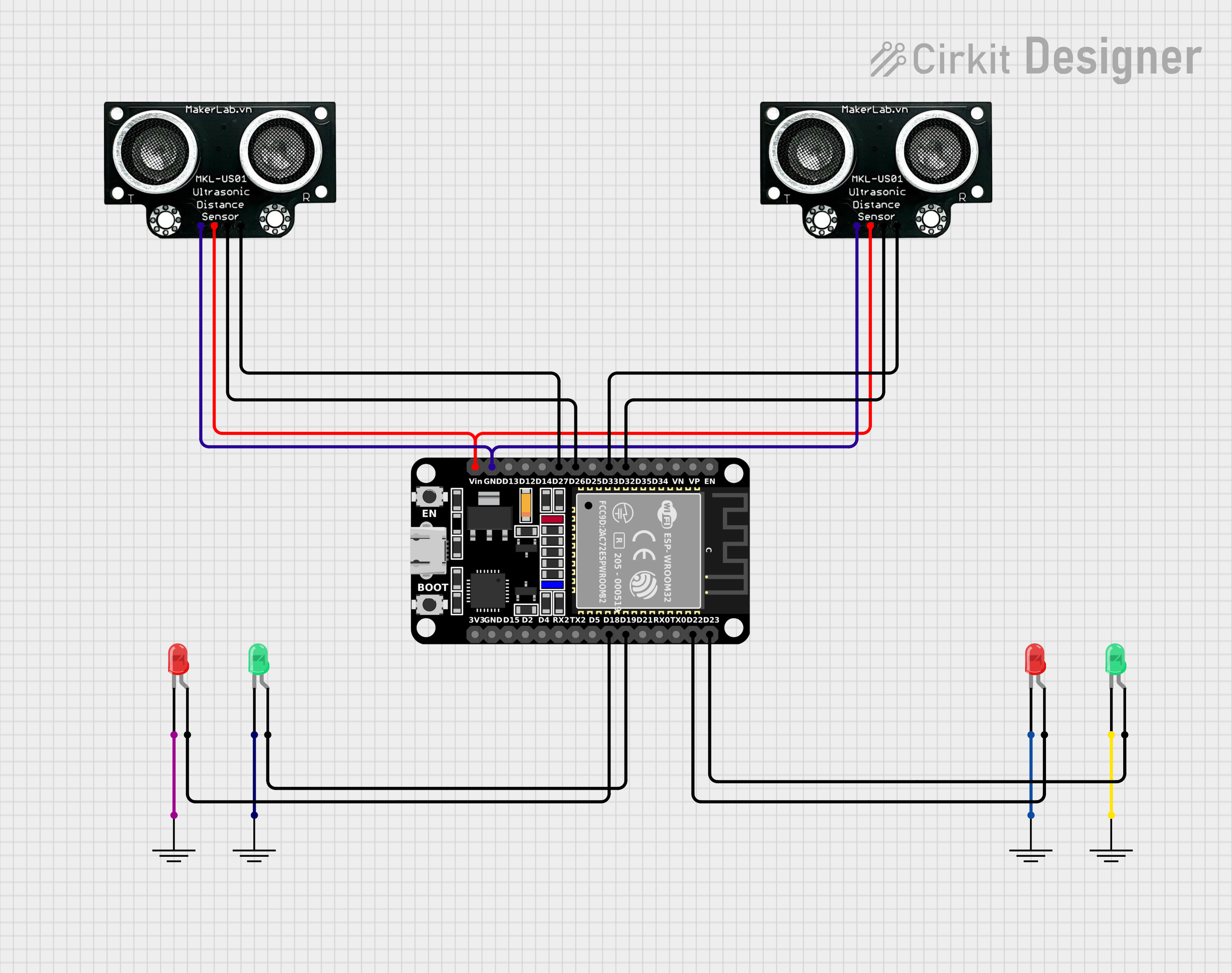

Explore Projects Built with MKE-M01_LED
Common Applications
- Status indicators in electronic circuits
- DIY projects and prototyping
- Decorative and ambient lighting
- Educational kits and demonstrations
- Low-power signaling in embedded systems
Technical Specifications
The following table outlines the key technical details of the MKE-M01_LED module:
| Parameter | Value |
|---|---|
| Operating Voltage | 2.0V - 3.3V |
| Forward Current (If) | 20mA (typical) |
| Power Consumption | ≤ 0.066W |
| Luminous Intensity | 1000 - 1500 mcd |
| Viewing Angle | 120° |
| Dimensions | 5mm (diameter) |
| Color Options | Red, Green, Blue, Yellow, White |
| Operating Temperature | -20°C to +70°C |
| Storage Temperature | -40°C to +85°C |
Pin Configuration
The MKE-M01_LED module has two pins:
| Pin | Name | Description |
|---|---|---|
| 1 | Anode (+) | Connect to the positive terminal of the power supply or microcontroller output. |
| 2 | Cathode (-) | Connect to the ground (GND) of the circuit. |
Note: A current-limiting resistor is required to prevent damage to the LED. The resistor value depends on the supply voltage and desired current.
Usage Instructions
How to Use the MKE-M01_LED in a Circuit
Determine the Supply Voltage: Identify the voltage source you will use (e.g., 5V from an Arduino UNO or a 3.3V power supply).
Calculate the Resistor Value: Use Ohm's Law to calculate the appropriate resistor value: [ R = \frac{V_{supply} - V_{forward}}{I_{forward}} ]
- (V_{supply}): Supply voltage (e.g., 5V)
- (V_{forward}): Forward voltage of the LED (e.g., 2.0V for red LED)
- (I_{forward}): Desired forward current (e.g., 20mA or 0.02A)
Example: For a 5V supply and a red LED with (V_{forward} = 2.0V): [ R = \frac{5V - 2.0V}{0.02A} = 150 , \Omega ]
Connect the LED:
- Connect the Anode (+) to the positive terminal of the power supply or microcontroller pin through the resistor.
- Connect the Cathode (-) to the ground (GND).
Test the Circuit: Power on the circuit and verify that the LED lights up.
Example: Connecting to an Arduino UNO
The following example demonstrates how to connect the MKE-M01_LED to an Arduino UNO and control it using a digital output pin.
Circuit Diagram
- Connect the Anode (+) of the LED to Arduino pin 9 through a 220Ω resistor.
- Connect the Cathode (-) to the Arduino GND pin.
Arduino Code
// MKE-M01_LED Example Code
// This code blinks the LED connected to pin 9 of the Arduino UNO.

const int ledPin = 9; // Define the pin connected to the LED

void setup() {
  pinMode(ledPin, OUTPUT); // Set the LED pin as an output
}

void loop() {
  digitalWrite(ledPin, HIGH); // Turn the LED on
  delay(1000);                // Wait for 1 second
  digitalWrite(ledPin, LOW);  // Turn the LED off
  delay(1000);                // Wait for 1 second
}
Important Considerations
- Always use a current-limiting resistor to protect the LED from excessive current.
- Ensure the operating voltage does not exceed the specified range (2.0V - 3.3V).
- Avoid exposing the LED to temperatures outside the operating range (-20°C to +70°C).
Troubleshooting and FAQs
Common Issues
LED Does Not Light Up:
- Cause: Incorrect polarity (Anode and Cathode reversed).
- Solution: Verify the connections and ensure the Anode is connected to the positive terminal.
LED is Dim:
- Cause: Resistor value is too high, limiting the current excessively.
- Solution: Recalculate the resistor value and use a lower resistance.
LED Burns Out:
- Cause: No current-limiting resistor or excessive supply voltage.
- Solution: Always use a resistor and ensure the supply voltage is within the specified range.
Flickering LED:
- Cause: Unstable power supply or loose connections.
- Solution: Check the power source and ensure all connections are secure.
FAQs
Q1: Can I connect the MKE-M01_LED directly to a 5V power supply?
A1: No, you must use a current-limiting resistor to prevent damage to the LED.
Q2: What resistor value should I use for a 3.3V supply?
A2: For a red LED with (V_{forward} = 2.0V) and (I_{forward} = 20mA):
[
R = \frac{3.3V - 2.0V}{0.02A} = 65 , \Omega
]
Use the closest standard resistor value (e.g., 68Ω).
Q3: Can I use the MKE-M01_LED with a PWM signal?
A3: Yes, the LED can be dimmed using a PWM signal from a microcontroller like an Arduino.
Q4: What is the maximum current the LED can handle?
A4: The maximum forward current is 20mA. Exceeding this value may damage the LED.
By following this documentation, you can effectively integrate the MKE-M01_LED into your projects and ensure optimal performance.