How to Use M01_LED: Examples, Pinouts, and Specs
Introduction
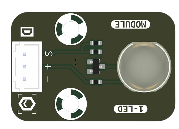
The M01_LED, manufactured by MakerEdu.vn (Part ID: LED), is a light-emitting diode (LED) designed to emit light when an electric current flows through it. This versatile component is widely used in electronics for visual indicators, displays, and decorative lighting. Its compact size, low power consumption, and long lifespan make it an essential component in a variety of applications.
Explore Projects Built with M01_LED
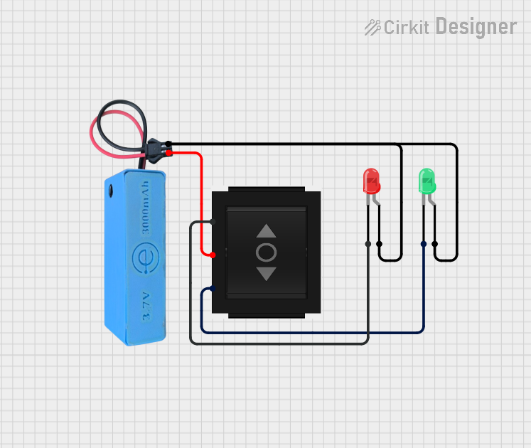
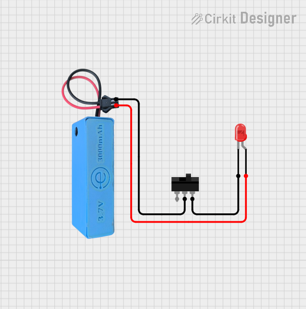
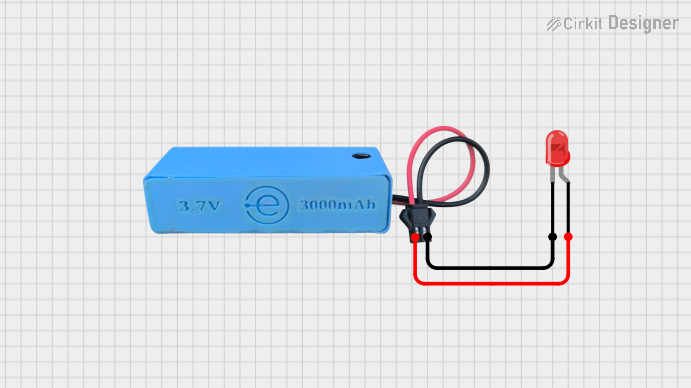

Explore Projects Built with M01_LED
Common Applications
- Power and status indicators in electronic devices
- Digital displays and signage
- Backlighting for LCDs and keypads
- Decorative and ambient lighting
- Prototyping and educational projects
Technical Specifications
The M01_LED is a general-purpose LED with the following specifications:
| Parameter | Value |
|---|---|
| Forward Voltage (Vf) | 2.0V - 2.2V (typical) |
| Forward Current (If) | 20mA (maximum) |
| Reverse Voltage (Vr) | 5V (maximum) |
| Power Dissipation | 50mW (maximum) |
| Wavelength (Color) | Red (620-630nm) |
| Viewing Angle | 30° - 60° |
| Operating Temperature | -40°C to +85°C |
| Package Type | 5mm round (THT) |
Pin Configuration
The M01_LED has two pins:
| Pin Name | Description |
|---|---|
| Anode (+) | Positive terminal (longer leg) |
| Cathode (-) | Negative terminal (shorter leg) |
Note: The longer leg of the LED is the anode, which connects to the positive voltage, while the shorter leg is the cathode, which connects to ground.
Usage Instructions
How to Use the M01_LED in a Circuit
Determine the Resistor Value: To prevent damage to the LED, always use a current-limiting resistor in series with the LED. The resistor value can be calculated using Ohm's Law: [ R = \frac{V_{supply} - V_f}{I_f} ] Where:
- ( V_{supply} ) is the supply voltage
- ( V_f ) is the forward voltage of the LED (2.0V - 2.2V)
- ( I_f ) is the forward current (20mA or 0.02A)
For example, if ( V_{supply} = 5V ): [ R = \frac{5V - 2.2V}{0.02A} = 140\Omega ] Use the nearest standard resistor value (e.g., 150Ω).
Connect the LED:
- Connect the anode (+) to the positive voltage through the resistor.
- Connect the cathode (-) to ground.
Power the Circuit: Apply the appropriate voltage to the circuit. The LED will emit light when current flows through it.
Example: Connecting M01_LED to an Arduino UNO
The M01_LED can be easily interfaced with an Arduino UNO for basic projects. Below is an example of how to blink the LED using Arduino:
Circuit Diagram
- Connect the anode (+) of the LED to Arduino digital pin 13 through a 220Ω resistor.
- Connect the cathode (-) of the LED to the Arduino GND pin.
Arduino Code
// M01_LED Blink Example
// This code blinks the M01_LED connected to pin 13 of the Arduino UNO.

void setup() {
  pinMode(13, OUTPUT); // Set pin 13 as an output pin
}

void loop() {
  digitalWrite(13, HIGH); // Turn the LED on
  delay(1000);            // Wait for 1 second
  digitalWrite(13, LOW);  // Turn the LED off
  delay(1000);            // Wait for 1 second
}
Best Practices
- Always use a current-limiting resistor to protect the LED.
- Avoid exceeding the maximum forward current (20mA) to prevent overheating.
- Ensure proper polarity when connecting the LED to a circuit.
- Use a heat sink or proper ventilation if the LED is used in high-power applications.
Troubleshooting and FAQs
Common Issues
LED Does Not Light Up:
- Cause: Incorrect polarity.
- Solution: Ensure the anode is connected to the positive voltage and the cathode to ground.
- Cause: No current-limiting resistor or incorrect resistor value.
- Solution: Verify the resistor value and connections.
- Cause: Incorrect polarity.
LED is Dim:
- Cause: Insufficient current.
- Solution: Check the resistor value and ensure it allows enough current (e.g., 20mA).
- Cause: Insufficient current.
LED Burns Out Quickly:
- Cause: Excessive current.
- Solution: Use a proper current-limiting resistor to limit the current to 20mA.
- Cause: Excessive current.
LED Flickers:
- Cause: Unstable power supply.
- Solution: Use a stable power source or add a capacitor to smooth out voltage fluctuations.
- Cause: Unstable power supply.
FAQs
Can I connect the M01_LED directly to a 5V power supply?
- No, always use a current-limiting resistor to prevent damage to the LED.
What happens if I reverse the polarity of the LED?
- The LED will not light up, but it will not be damaged as long as the reverse voltage does not exceed 5V.
Can I use the M01_LED with a 3.3V microcontroller?
- Yes, but ensure you calculate the appropriate resistor value for the 3.3V supply.
What is the lifespan of the M01_LED?
- The LED has a typical lifespan of over 50,000 hours under normal operating conditions.
By following this documentation, you can effectively use the M01_LED in your projects and troubleshoot common issues with ease.