
How to Use ATS 230V 2P external trigger: Examples, Pinouts, and Specs
 Design with ATS 230V 2P external trigger in Cirkit Designer
Introduction
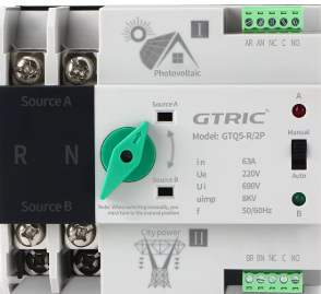
The ATS 230V 2P External Trigger is an Automatic Transfer Switch designed for 230V applications with a 2-pole configuration. This device ensures uninterrupted power supply by automatically switching between two power sources, such as a primary utility grid and a backup generator. It is particularly useful in residential, commercial, and industrial settings where power continuity is critical.
Explore Projects Built with ATS 230V 2P external trigger
 Open Project in Cirkit Designer
 Open Project in Cirkit Designer
 Open Project in Cirkit Designer
 Open Project in Cirkit Designer
Explore Projects Built with ATS 230V 2P external trigger
Open Project in Cirkit DesignerOpen Project in Cirkit DesignerOpen Project in Cirkit DesignerOpen Project in Cirkit DesignerCommon Applications and Use Cases
- Backup power systems for homes and offices
- Industrial equipment requiring continuous power
- Data centers and server rooms
- Hospitals and medical facilities
- Renewable energy systems (e.g., solar or wind power integration)
Technical Specifications
Key Technical Details
| Parameter | Specification |
|---|---|
| Rated Voltage | 230V AC |
| Rated Current | 16A, 32A, or 63A (model-specific) |
| Poles | 2 (Double Pole) |
| Frequency | 50/60 Hz |
| Switching Time | ≤ 3 seconds |
| Control Method | External trigger signal |
| Operating Temperature | -20°C to +55°C |
| Insulation Resistance | ≥ 2MΩ |
| Mechanical Life | ≥ 10,000 cycles |
| Electrical Life | ≥ 5,000 cycles |
Pin Configuration and Descriptions
The ATS 230V 2P External Trigger typically features the following terminal connections:
| Terminal Label | Description |
|---|---|
| L1 (Input) | Live input from primary power source |
| N1 (Input) | Neutral input from primary power source |
| L2 (Input) | Live input from secondary power source |
| N2 (Input) | Neutral input from secondary power source |
| L (Output) | Live output to the load |
| N (Output) | Neutral output to the load |
| Trigger+ | Positive terminal for external trigger |
| Trigger- | Negative terminal for external trigger |
Usage Instructions
How to Use the Component in a Circuit
Wiring the ATS:
- Connect the primary power source (e.g., utility grid) to terminals
L1andN1. - Connect the secondary power source (e.g., generator) to terminals
L2andN2. - Connect the load (e.g., appliances or equipment) to terminals
LandN. - Connect the external trigger signal to
Trigger+andTrigger-.
- Connect the primary power source (e.g., utility grid) to terminals
Power Source Selection:
- The ATS will automatically switch to the secondary power source if the primary source fails.
- When the primary source is restored, the ATS will switch back to it after a brief delay.
External Trigger:
- Use an external control signal (e.g., from a microcontroller or relay) to manually trigger the switch between power sources if needed.
Important Considerations and Best Practices
- Ensure that the ATS is rated for the current and voltage of your application.
- Use proper circuit breakers or fuses to protect the ATS and connected equipment.
- Verify all connections are secure and insulated to prevent short circuits or electrical hazards.
- Test the ATS functionality before deploying it in a critical application.
- Avoid exceeding the rated switching cycles to prolong the device's lifespan.
Example: Connecting the ATS to an Arduino UNO
The ATS can be controlled using an Arduino UNO to send an external trigger signal. Below is an example code snippet:
// Example code to control ATS 230V 2P External Trigger using Arduino UNO
// This code sends a HIGH signal to the ATS trigger pin to switch power sources.

const int triggerPin = 7; // Pin connected to ATS Trigger+

void setup() {
  pinMode(triggerPin, OUTPUT); // Set trigger pin as output
  digitalWrite(triggerPin, LOW); // Initialize trigger pin to LOW
}

void loop() {
  // Simulate switching to secondary power source
  digitalWrite(triggerPin, HIGH); // Send HIGH signal to ATS
  delay(5000); // Keep secondary source active for 5 seconds

  // Switch back to primary power source
  digitalWrite(triggerPin, LOW); // Send LOW signal to ATS
  delay(5000); // Wait for 5 seconds before next cycle
}
Note: Ensure the Arduino's ground (GND) is connected to the ATS Trigger- terminal.
Troubleshooting and FAQs
Common Issues and Solutions
| Issue | Possible Cause | Solution |
|---|---|---|
| ATS does not switch power sources | Incorrect wiring or loose connections | Verify all connections and wiring. |
| Delayed switching | Faulty external trigger signal | Check the trigger signal source. |
| No output to the load | Power sources not supplying voltage | Ensure both power sources are active. |
| Frequent switching between sources | Unstable primary power source | Stabilize the primary power source. |
FAQs
Can the ATS handle inductive loads?
- Yes, but ensure the load's inrush current does not exceed the ATS's rated current.
What happens if both power sources fail?
- The ATS will not supply power to the load until at least one source is restored.
Can I manually override the ATS?
- Yes, by using the external trigger terminals or a manual bypass switch (if available).
Is the ATS compatible with renewable energy systems?
- Yes, it can switch between renewable energy sources (e.g., solar) and the utility grid.
By following this documentation, users can effectively integrate the ATS 230V 2P External Trigger into their power systems for reliable and seamless operation.