Cirkit Designer Logo
Cirkit Designer
Your all-in-one circuit design IDE
Home / 
Component Documentation

How to Use Microstep Driver: Examples, Pinouts, and Specs

Image of Microstep Driver
Cirkit Designer LogoDesign with Microstep Driver in Cirkit Designer

Introduction

The CW-5045 Microstep Driver by CNC4YOU is an advanced electronic device designed to control stepper motors with high precision. By dividing each full step of a stepper motor into smaller microsteps, this driver enables smoother motion, reduced vibration, and improved positional accuracy. It is ideal for applications requiring precise motor control, such as CNC machines, 3D printers, robotics, and automated systems.

Explore Projects Built with Microstep Driver

Use Cirkit Designer to design, explore, and prototype these projects online. Some projects support real-time simulation. Click "Open Project" to start designing instantly!
CNC Machine Control System with Dual tb6600 Stepper Drivers and MAch3 USB Interface
Image of Jayshree CNC: A project utilizing Microstep Driver in a practical application
This circuit appears to be a control system for a CNC machine or similar automated equipment. It includes two tb6600 Micro Stepping Motor Drivers for controlling stepper motors, a DC power source with a step-down buck converter to provide the necessary voltage levels, and a 4-channel relay module for switching higher power loads. The MAch3 CNC USB interface suggests the system is designed to interface with computer numerical control software, and the RMCS_3001 BLDC Driver indicates the presence of a brushless DC motor control. The Tiva C launchpad microcontroller and various connectors imply that the system is modular and may be programmable for specific automation tasks.
Cirkit Designer LogoOpen Project in Cirkit Designer
ATmega328P Microcontroller-Driven Stepper Motor with DRV8825
Image of Shutter for laser: A project utilizing Microstep Driver in a practical application
This circuit is designed to control a bipolar stepper motor using a DRV8825 stepper motor driver, which is interfaced with a Nano 3.0 ATmega328P microcontroller. The microcontroller sends step and direction signals to the DRV8825, which in turn drives the stepper motor's coils. Power is supplied to the system through a 5V adapter for the logic and a DC power source for the motor, with an electrolytic capacitor for voltage smoothing on the motor supply.
Cirkit Designer LogoOpen Project in Cirkit Designer
Teensy-Controlled Stepper Motor and Servo Actuation System
Image of Prototype Robotic Arm: A project utilizing Microstep Driver in a practical application
This circuit controls a bipolar stepper motor using an A4988 Stepper Motor Driver, which is interfaced with a Teensy 4.1 microcontroller. The Teensy sends step and direction signals to the driver, while the driver's RESET and SLEEP pins are tied together, likely for simplified control. Additionally, the circuit includes an Adafruit PCA9685 PWM Servo Breakout board, which is connected to a servo motor and communicates with the Teensy via I2C, and both the driver and the breakout board are powered by separate power supplies with decoupling provided by an electrolytic capacitor.
Cirkit Designer LogoOpen Project in Cirkit Designer
Arduino-Controlled Stepper Motor with LCD Interface and Rotary Encoder
Image of AC Servo Motor: A project utilizing Microstep Driver in a practical application
This circuit is designed to control a bipolar stepper motor using an Arduino Mega 2560 microcontroller and a STEPPERONLINE DM542T driver. The Arduino interfaces with a 20x4 LCD display over I2C for user feedback, a membrane matrix keypad for user input, and a rotary encoder for precise control inputs. The power supply provides the necessary voltage and current to drive the stepper motor through the DM542T driver.
Cirkit Designer LogoOpen Project in Cirkit Designer

Explore Projects Built with Microstep Driver

Use Cirkit Designer to design, explore, and prototype these projects online. Some projects support real-time simulation. Click "Open Project" to start designing instantly!
Image of Jayshree CNC: A project utilizing Microstep Driver in a practical application
CNC Machine Control System with Dual tb6600 Stepper Drivers and MAch3 USB Interface
This circuit appears to be a control system for a CNC machine or similar automated equipment. It includes two tb6600 Micro Stepping Motor Drivers for controlling stepper motors, a DC power source with a step-down buck converter to provide the necessary voltage levels, and a 4-channel relay module for switching higher power loads. The MAch3 CNC USB interface suggests the system is designed to interface with computer numerical control software, and the RMCS_3001 BLDC Driver indicates the presence of a brushless DC motor control. The Tiva C launchpad microcontroller and various connectors imply that the system is modular and may be programmable for specific automation tasks.
Cirkit Designer LogoOpen Project in Cirkit Designer
Image of Shutter for laser: A project utilizing Microstep Driver in a practical application
ATmega328P Microcontroller-Driven Stepper Motor with DRV8825
This circuit is designed to control a bipolar stepper motor using a DRV8825 stepper motor driver, which is interfaced with a Nano 3.0 ATmega328P microcontroller. The microcontroller sends step and direction signals to the DRV8825, which in turn drives the stepper motor's coils. Power is supplied to the system through a 5V adapter for the logic and a DC power source for the motor, with an electrolytic capacitor for voltage smoothing on the motor supply.
Cirkit Designer LogoOpen Project in Cirkit Designer
Image of Prototype Robotic Arm: A project utilizing Microstep Driver in a practical application
Teensy-Controlled Stepper Motor and Servo Actuation System
This circuit controls a bipolar stepper motor using an A4988 Stepper Motor Driver, which is interfaced with a Teensy 4.1 microcontroller. The Teensy sends step and direction signals to the driver, while the driver's RESET and SLEEP pins are tied together, likely for simplified control. Additionally, the circuit includes an Adafruit PCA9685 PWM Servo Breakout board, which is connected to a servo motor and communicates with the Teensy via I2C, and both the driver and the breakout board are powered by separate power supplies with decoupling provided by an electrolytic capacitor.
Cirkit Designer LogoOpen Project in Cirkit Designer
Image of AC Servo Motor: A project utilizing Microstep Driver in a practical application
Arduino-Controlled Stepper Motor with LCD Interface and Rotary Encoder
This circuit is designed to control a bipolar stepper motor using an Arduino Mega 2560 microcontroller and a STEPPERONLINE DM542T driver. The Arduino interfaces with a 20x4 LCD display over I2C for user feedback, a membrane matrix keypad for user input, and a rotary encoder for precise control inputs. The power supply provides the necessary voltage and current to drive the stepper motor through the DM542T driver.
Cirkit Designer LogoOpen Project in Cirkit Designer

Common Applications

  • CNC machines for precise cutting, milling, and engraving
  • 3D printers for accurate layer deposition
  • Robotics for smooth and controlled motion
  • Conveyor systems in industrial automation
  • Camera sliders and other motion control systems

Technical Specifications

The following table outlines the key technical details of the CW-5045 Microstep Driver:

Parameter Specification
Input Voltage Range 20V to 50V DC
Output Current Range 1.5A to 4.5A (adjustable)
Microstep Resolution 1, 2, 4, 8, 16, 32 (selectable)
Control Signal Voltage 5V (compatible with most controllers)
Step Frequency Range 0 to 200 kHz
Operating Temperature -10°C to +45°C
Dimensions 118mm x 75.5mm x 34mm
Weight 280g

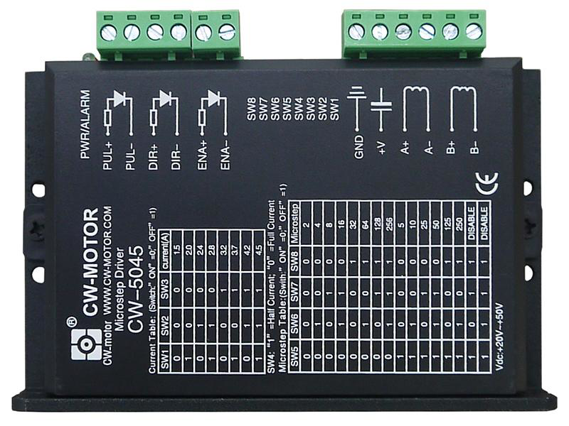
Pin Configuration and Descriptions

The CW-5045 Microstep Driver has the following pin configuration:

Input Signal Pins

Pin Name Description
PUL+ Pulse signal input (positive terminal)
PUL- Pulse signal input (negative terminal)
DIR+ Direction signal input (positive terminal)
DIR- Direction signal input (negative terminal)
ENA+ Enable signal input (positive terminal) (optional)
ENA- Enable signal input (negative terminal) (optional)

Motor Output Pins

Pin Name Description
A+ Motor coil A positive terminal
A- Motor coil A negative terminal
B+ Motor coil B positive terminal
B- Motor coil B negative terminal

Power Input Pins

Pin Name Description
VCC Power supply positive terminal (20V to 50V DC)
GND Power supply ground terminal

Usage Instructions

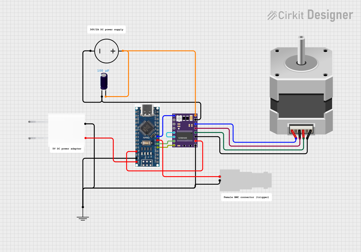
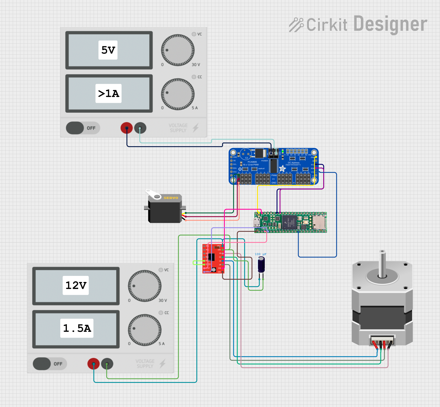
Connecting the CW-5045 Microstep Driver

  1. Power Supply: Connect a DC power supply (20V to 50V) to the VCC and GND pins. Ensure the power supply can provide sufficient current for the stepper motor.
  2. Stepper Motor: Connect the stepper motor's coils to the A+, A-, B+, and B- pins. Refer to the motor's datasheet to identify the correct coil pairs.
  3. Control Signals: Connect the PUL, DIR, and ENA pins to a microcontroller or CNC controller. Use the "+" and "-" terminals as appropriate for your control signal voltage.
  4. Microstep and Current Settings: Use the DIP switches on the driver to configure the microstep resolution and output current. Refer to the driver’s user manual for DIP switch settings.

Example: Connecting to an Arduino UNO

The CW-5045 can be easily interfaced with an Arduino UNO for stepper motor control. Below is an example Arduino sketch:

// Example code to control a stepper motor using the CW-5045 Microstep Driver
// Connect PUL+ to Arduino pin 9, DIR+ to pin 8, and ENA+ to pin 7
// Connect PUL-, DIR-, and ENA- to Arduino GND

#define PUL_PIN 9  // Pulse signal pin
#define DIR_PIN 8  // Direction signal pin
#define ENA_PIN 7  // Enable signal pin

void setup() {
  pinMode(PUL_PIN, OUTPUT); // Set pulse pin as output
  pinMode(DIR_PIN, OUTPUT); // Set direction pin as output
  pinMode(ENA_PIN, OUTPUT); // Set enable pin as output

  digitalWrite(ENA_PIN, LOW); // Enable the driver (LOW = enabled)
}

void loop() {
  digitalWrite(DIR_PIN, HIGH); // Set direction (HIGH = one direction, LOW = reverse)

  // Generate pulses to move the motor
  for (int i = 0; i < 200; i++) { // 200 pulses for one revolution (1.8° step motor)
    digitalWrite(PUL_PIN, HIGH); // Pulse HIGH
    delayMicroseconds(500);      // Delay for pulse width (500 µs)
    digitalWrite(PUL_PIN, LOW);  // Pulse LOW
    delayMicroseconds(500);      // Delay for pulse interval
  }

  delay(1000); // Wait 1 second before reversing direction

  digitalWrite(DIR_PIN, LOW); // Reverse direction

  // Generate pulses to move the motor in the opposite direction
  for (int i = 0; i < 200; i++) {
    digitalWrite(PUL_PIN, HIGH);
    delayMicroseconds(500);
    digitalWrite(PUL_PIN, LOW);
    delayMicroseconds(500);
  }

  delay(1000); // Wait 1 second before repeating
}

Important Considerations

  • Power Supply: Ensure the power supply voltage and current match the requirements of both the driver and the stepper motor.
  • Heat Dissipation: The driver may heat up during operation. Use a heatsink or cooling fan if necessary.
  • Signal Noise: Use shielded cables for control signals to minimize noise and interference.
  • Microstep Settings: Choose an appropriate microstep resolution based on the application's precision and speed requirements.

Troubleshooting and FAQs

Common Issues and Solutions

  1. Motor Not Moving:

    • Check the power supply connections and ensure the voltage is within the specified range.
    • Verify the control signal connections (PUL, DIR, ENA) and ensure the microcontroller is generating pulses.
    • Ensure the motor coils are correctly connected to the driver.
  2. Motor Vibrates but Does Not Rotate:

    • Verify the motor coil connections. Incorrect wiring can cause the motor to vibrate without rotating.
    • Check the microstep and current settings on the DIP switches.
  3. Driver Overheating:

    • Ensure proper ventilation and consider adding a heatsink or cooling fan.
    • Verify that the output current setting matches the motor's rated current.
  4. Inconsistent Motor Movement:

    • Check for noise or interference in the control signal lines.
    • Use shielded cables and ensure proper grounding.

FAQs

Q: Can the CW-5045 drive any stepper motor?
A: The CW-5045 is compatible with most 2-phase and 4-phase stepper motors, provided their voltage and current ratings are within the driver's specifications.

Q: How do I select the microstep resolution?
A: Use the DIP switches on the driver to configure the microstep resolution. Refer to the user manual for the DIP switch settings.

Q: Is the ENA signal mandatory?
A: No, the ENA signal is optional. If not used, leave the ENA+ and ENA- pins disconnected or set ENA+ to HIGH to enable the driver.

Q: Can I use the CW-5045 with a 12V power supply?
A: No, the minimum input voltage for the CW-5045 is 20V. Using a lower voltage may damage the driver or result in improper operation.