Cirkit Designer Logo
Cirkit Designer
Your all-in-one circuit design IDE
Home / 
Component Documentation

How to Use Brushless Motor: Examples, Pinouts, and Specs

Image of Brushless Motor
Cirkit Designer LogoDesign with Brushless Motor in Cirkit Designer

Introduction

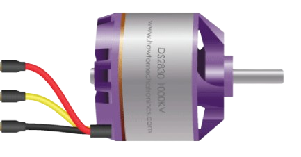
The Brushless Motor A2212 is an efficient and reliable electric motor commonly used in a variety of applications, including drones, model aircraft, and small electric vehicles. Unlike traditional brushed motors, the A2212 operates using electronic commutation, which eliminates the need for physical brushes and results in less wear and tear, longer lifespan, and improved performance.

Explore Projects Built with Brushless Motor

Use Cirkit Designer to design, explore, and prototype these projects online. Some projects support real-time simulation. Click "Open Project" to start designing instantly!
Arduino UNO Controlled BLDC Motor Stabilization System with MPU-6050 IMU
Image of rfss: A project utilizing Brushless Motor in a practical application
This circuit is designed to control a brushless DC (BLDC) motor using an Arduino UNO microcontroller and an Electronic Speed Controller (ESC). The Arduino reads orientation data from an MPU-6050 inertial measurement unit (IMU) and adjusts the motor's speed to stabilize a system, likely a reaction flywheel stabilization system. Power is supplied by a lipo battery, with voltage regulation provided by an AMS1117 voltage regulator.
Cirkit Designer LogoOpen Project in Cirkit Designer
Wi-Fi Controlled Brushless Motor System with ESP32 and ESC
Image of BRUSHLESS DC MOTOR: A project utilizing Brushless Motor in a practical application
This circuit controls a brushless motor using an ESP32 microcontroller and an Electronic Speed Controller (ESC). The ESP32 sends control signals to the ESC, which regulates the power from a 12V power supply to drive the motor.
Cirkit Designer LogoOpen Project in Cirkit Designer
Quadcopter BLDC Motor Control System with Radio Receiver
Image of rc car: A project utilizing Brushless Motor in a practical application
This circuit is designed to control four Brushless DC (BLDC) motors using corresponding Electronic Speed Controllers (ESCs). Each ESC receives power from a shared LiPo battery and control signals from an FS-CT6B receiver, which likely receives input from a remote transmitter for wireless control. The ESCs regulate the power supplied to the motors based on the received signals, enabling precise speed and direction control of the motors, typically used in applications such as drones or remote-controlled vehicles.
Cirkit Designer LogoOpen Project in Cirkit Designer
ESP32-Controlled Dual BLDC Motor & DC Gear Motor Circuit with Bluetooth Interface
Image of major boat: A project utilizing Brushless Motor in a practical application
This circuit is designed to control two brushless DC (BLDC) motors via electronic speed controllers (ESCs) and a DC mini metal gear motor, all powered by separate battery sources. The ESP32 microcontroller is programmed to receive Bluetooth commands to adjust the speed of the BLDC motors and the direction of the DC motor, as well as to control additional servos and a relay for auxiliary functions. The circuit is likely part of a remotely controlled vehicle or boat, with the capability to vary speed and direction, and to activate additional mechanisms or accessories.
Cirkit Designer LogoOpen Project in Cirkit Designer

Explore Projects Built with Brushless Motor

Use Cirkit Designer to design, explore, and prototype these projects online. Some projects support real-time simulation. Click "Open Project" to start designing instantly!
Image of rfss: A project utilizing Brushless Motor in a practical application
Arduino UNO Controlled BLDC Motor Stabilization System with MPU-6050 IMU
This circuit is designed to control a brushless DC (BLDC) motor using an Arduino UNO microcontroller and an Electronic Speed Controller (ESC). The Arduino reads orientation data from an MPU-6050 inertial measurement unit (IMU) and adjusts the motor's speed to stabilize a system, likely a reaction flywheel stabilization system. Power is supplied by a lipo battery, with voltage regulation provided by an AMS1117 voltage regulator.
Cirkit Designer LogoOpen Project in Cirkit Designer
Image of BRUSHLESS DC MOTOR: A project utilizing Brushless Motor in a practical application
Wi-Fi Controlled Brushless Motor System with ESP32 and ESC
This circuit controls a brushless motor using an ESP32 microcontroller and an Electronic Speed Controller (ESC). The ESP32 sends control signals to the ESC, which regulates the power from a 12V power supply to drive the motor.
Cirkit Designer LogoOpen Project in Cirkit Designer
Image of rc car: A project utilizing Brushless Motor in a practical application
Quadcopter BLDC Motor Control System with Radio Receiver
This circuit is designed to control four Brushless DC (BLDC) motors using corresponding Electronic Speed Controllers (ESCs). Each ESC receives power from a shared LiPo battery and control signals from an FS-CT6B receiver, which likely receives input from a remote transmitter for wireless control. The ESCs regulate the power supplied to the motors based on the received signals, enabling precise speed and direction control of the motors, typically used in applications such as drones or remote-controlled vehicles.
Cirkit Designer LogoOpen Project in Cirkit Designer
Image of major boat: A project utilizing Brushless Motor in a practical application
ESP32-Controlled Dual BLDC Motor & DC Gear Motor Circuit with Bluetooth Interface
This circuit is designed to control two brushless DC (BLDC) motors via electronic speed controllers (ESCs) and a DC mini metal gear motor, all powered by separate battery sources. The ESP32 microcontroller is programmed to receive Bluetooth commands to adjust the speed of the BLDC motors and the direction of the DC motor, as well as to control additional servos and a relay for auxiliary functions. The circuit is likely part of a remotely controlled vehicle or boat, with the capability to vary speed and direction, and to activate additional mechanisms or accessories.
Cirkit Designer LogoOpen Project in Cirkit Designer

Common Applications and Use Cases

  • Radio-controlled (RC) aircraft and drones
  • Small electric vehicles
  • Robotics
  • DIY electronics projects

Technical Specifications

Key Technical Details

  • Nominal Voltage: 7.4V - 11.1V
  • Maximum Current: 12A
  • Power Rating: Up to 150W
  • KV Rating: 2200 RPM/V
  • Efficiency: >70%
  • Motor Dimensions: 27.5mm x 30mm
  • Shaft Diameter: 3.17mm
  • Weight: 52g

Pin Configuration and Descriptions

Pin Number Description Notes
1 Phase A Output Connect to ESC Phase A
2 Phase B Output Connect to ESC Phase B
3 Phase C Output Connect to ESC Phase C

Note: ESC stands for Electronic Speed Controller, which is required to drive the brushless motor.

Usage Instructions

How to Use the Component in a Circuit

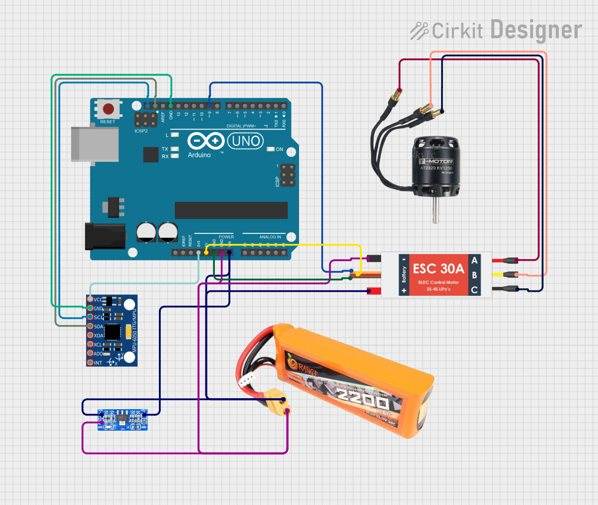
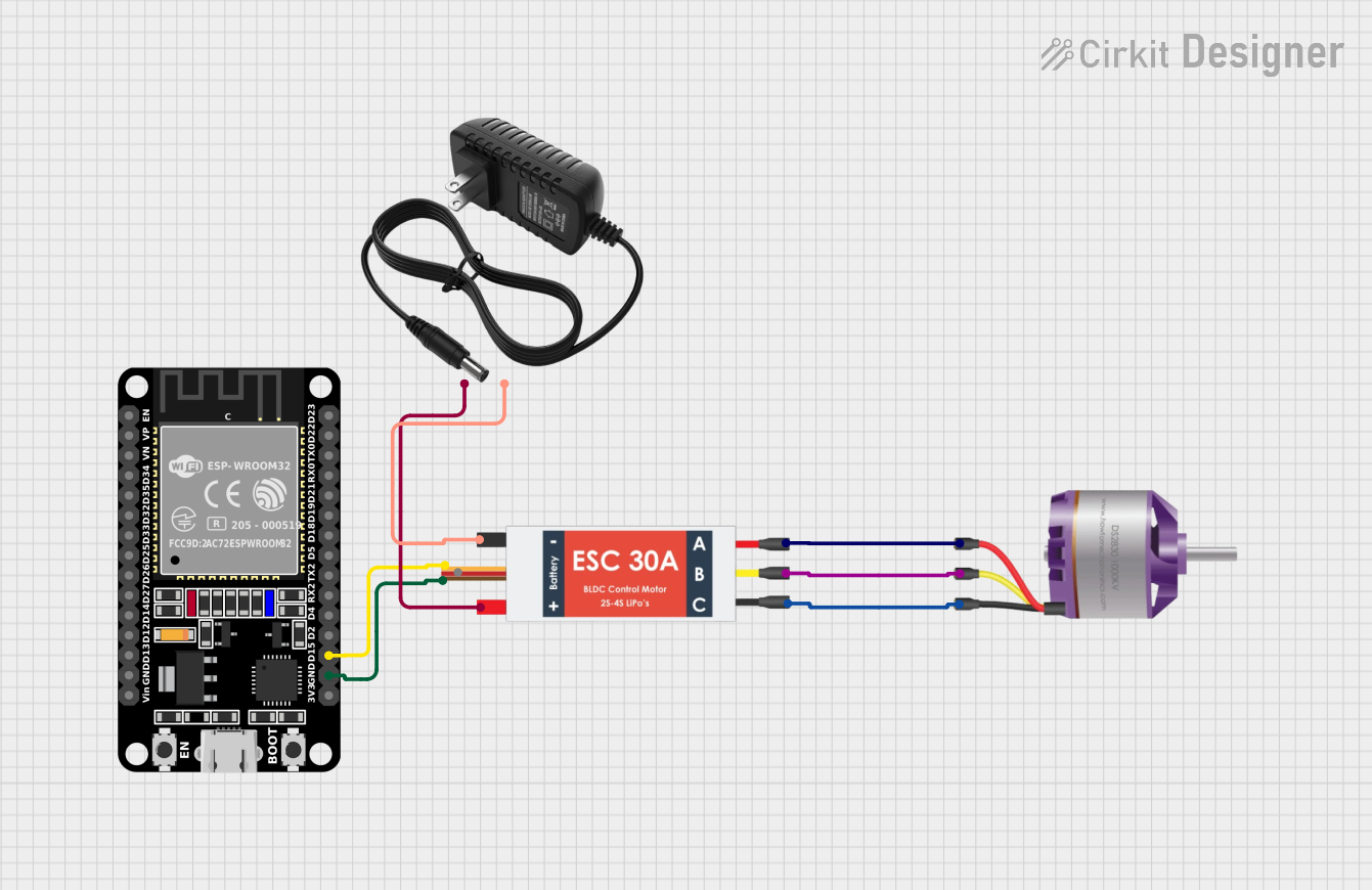
  1. Connect the Motor to an ESC: The three output wires of the A2212 motor must be connected to the corresponding phases of an appropriate Electronic Speed Controller (ESC). The order of connection can be changed to reverse the motor direction if needed.

  2. Power Supply: Ensure that the power supply voltage is within the specified range for the motor. Connect the power supply to the ESC according to the ESC's documentation.

  3. Control Signal: The ESC requires a control signal, typically a PWM signal, which can be generated by a microcontroller like an Arduino UNO.

  4. Mounting the Motor: Secure the motor to your application using appropriate mounting hardware, ensuring that it is firmly attached and that the rotating parts can move freely.

Important Considerations and Best Practices

  • Current Rating: Do not exceed the maximum current rating of the motor to prevent overheating and potential damage.
  • Propeller Balance: If using the motor with a propeller, ensure the propeller is well-balanced to minimize vibrations.
  • Cooling: Provide adequate cooling for the motor during operation, especially under high load conditions.
  • ESC Calibration: Calibrate the ESC according to its manual to ensure proper operation with the motor.

Troubleshooting and FAQs

Common Issues

  • Motor not spinning: Check connections between the motor and ESC, and ensure the power supply is within the specified range.
  • Overheating: Reduce the load on the motor or improve cooling.
  • Vibrations: Check that the propeller or any attached components are balanced and securely mounted.

Solutions and Tips for Troubleshooting

  • Reversing Motor Direction: Swap any two motor wires connected to the ESC to reverse the direction of rotation.
  • No Response to Control Signal: Verify that the PWM signal from the microcontroller is within the ESC's accepted range and that the ESC is properly calibrated.

FAQs

Q: Can I run the A2212 motor without an ESC? A: No, an ESC is required to provide the correct sequence of power to the motor phases.

Q: What is the maximum propeller size I can use with this motor? A: The maximum propeller size depends on the application and the power supply. Consult the motor's datasheet and the propeller's specifications for compatibility.

Q: How do I know if my ESC is compatible with this motor? A: Ensure that the ESC can handle the motor's voltage and current requirements. It should also be capable of driving brushless motors.

Example Code for Arduino UNO

Below is an example code snippet for controlling the A2212 motor using an Arduino UNO and an ESC. This code assumes the ESC is connected to pin 9 of the Arduino and that the ESC has been calibrated to recognize the Arduino's PWM signal range.

#include <Servo.h>

Servo esc; // Create a servo object to control the ESC

void setup() {
  esc.attach(9); // Attach the ESC on pin 9
  esc.writeMicroseconds(1000); // Send the minimum signal to the ESC
  delay(1000); // Wait for 1 second
}

void loop() {
  int throttle = 1500; // Set the throttle signal (microseconds)
  esc.writeMicroseconds(throttle); // Send the throttle signal to the ESC
  delay(10000); // Run the motor at the set throttle for 10 seconds

  esc.writeMicroseconds(1000); // Stop the motor by sending the minimum signal
  delay(5000); // Wait for 5 seconds before the next loop iteration
}

Note: The writeMicroseconds function is used to send precise control signals to the ESC. The values may need to be adjusted based on the ESC's calibration.

Remember to follow the ESC's calibration procedure before running this code to ensure the ESC recognizes the PWM signal range from the Arduino.