
How to Use Timer Relay Programmable: Examples, Pinouts, and Specs
 Design with Timer Relay Programmable in Cirkit Designer
Introduction
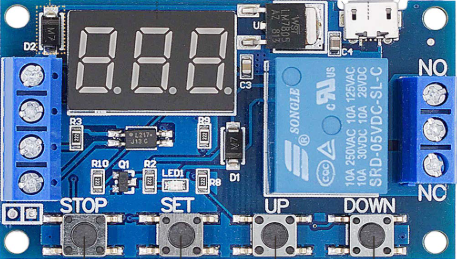
The Timer Relay Programmable by Valefod is an electromechanical device designed to control the timing of electrical circuits. This versatile component allows users to program specific time delays for turning circuits on or off, making it an essential tool for automation, control systems, and time-based operations. Its programmable nature ensures flexibility and precision in a wide range of applications.
Explore Projects Built with Timer Relay Programmable
 Open Project in Cirkit Designer
 Open Project in Cirkit Designer
 Open Project in Cirkit Designer
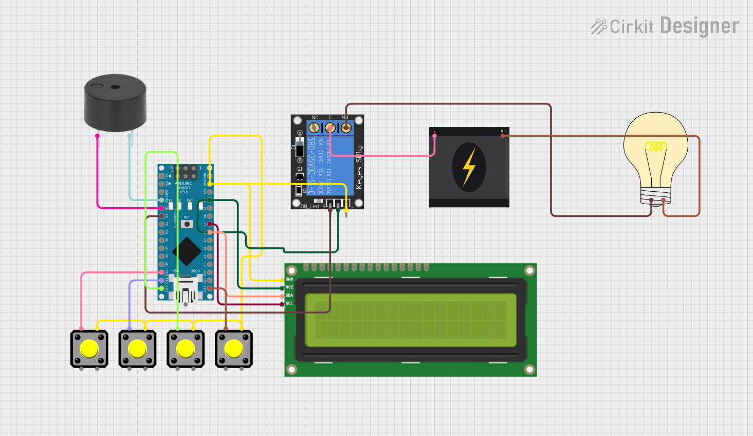 Open Project in Cirkit Designer
Explore Projects Built with Timer Relay Programmable
Open Project in Cirkit DesignerOpen Project in Cirkit DesignerOpen Project in Cirkit DesignerOpen Project in Cirkit DesignerCommon Applications and Use Cases
- Industrial automation systems
- Home automation (e.g., lighting control, irrigation systems)
- Motor control and protection
- Sequential control in manufacturing processes
- Delayed power-on or power-off for sensitive equipment
Technical Specifications
The following table outlines the key technical details of the Valefod Timer Relay Programmable:
| Parameter | Specification |
|---|---|
| Operating Voltage | 6V to 30V DC |
| Maximum Load Current | 10A |
| Relay Type | SPDT (Single Pole Double Throw) |
| Timing Range | 0.1 seconds to 999 minutes |
| Display Type | LED digital display |
| Programming Modes | 18 modes (e.g., delay on, delay off) |
| Power Consumption | < 0.5W |
| Dimensions | 60mm x 34mm x 12mm |
| Operating Temperature | -40°C to 85°C |
Pin Configuration and Descriptions
The Timer Relay Programmable has the following pin configuration:
| Pin Name | Description |
|---|---|
| VCC | Positive power supply input (6V to 30V DC). |
| GND | Ground connection for the power supply. |
| NO | Normally Open terminal of the relay. Connect the load to this terminal. |
| COM | Common terminal of the relay. |
| NC | Normally Closed terminal of the relay. |
Usage Instructions
How to Use the Timer Relay in a Circuit
- Power the Timer Relay: Connect the VCC pin to a DC power source (6V to 30V) and the GND pin to the ground.
- Connect the Load:
- For a normally open (NO) configuration, connect one terminal of the load to the NO pin and the other terminal to the power source.
- For a normally closed (NC) configuration, connect one terminal of the load to the NC pin and the other terminal to the power source.
- Ensure the COM pin is connected to the appropriate power or ground line, depending on the circuit design.
- Set the Timing Parameters:
- Use the onboard buttons to program the desired timing mode and delay duration.
- Refer to the Valefod Timer Relay manual for detailed instructions on programming the 18 available modes.
- Test the Circuit: Power on the system and verify that the relay operates according to the programmed timing.
Important Considerations and Best Practices
- Voltage Compatibility: Ensure the operating voltage of the relay matches the power supply to avoid damage.
- Load Ratings: Do not exceed the maximum load current of 10A to prevent overheating or relay failure.
- Isolation: Use proper electrical isolation techniques when working with high-power loads.
- Debouncing: If the relay is used in conjunction with a microcontroller, consider implementing software debouncing to handle relay switching noise.
Example: Using the Timer Relay with Arduino UNO
The Timer Relay Programmable can be easily integrated with an Arduino UNO for automation tasks. Below is an example code snippet to control the relay:
// Example: Controlling the Timer Relay Programmable with Arduino UNO
// Connect the relay's VCC and GND to the Arduino's 5V and GND pins.
// Connect the relay's COM and NO pins to the load circuit.

const int relayPin = 7; // Define the Arduino pin connected to the relay module

void setup() {
  pinMode(relayPin, OUTPUT); // Set the relay pin as an output
  digitalWrite(relayPin, LOW); // Ensure the relay is off at startup
}

void loop() {
  digitalWrite(relayPin, HIGH); // Turn the relay on
  delay(5000); // Keep the relay on for 5 seconds
  digitalWrite(relayPin, LOW); // Turn the relay off
  delay(5000); // Keep the relay off for 5 seconds
}
Notes:
- Replace
relayPinwith the actual pin number connected to the relay. - Adjust the
delay()values to modify the on/off timing.
Troubleshooting and FAQs
Common Issues and Solutions
Relay Not Switching:
- Cause: Insufficient power supply or incorrect wiring.
- Solution: Verify the power supply voltage (6V to 30V DC) and check all connections.
Load Not Operating:
- Cause: Incorrect connection of the load to the relay terminals.
- Solution: Ensure the load is properly connected to the NO or NC terminal and the COM terminal.
Relay Stuck in One State:
- Cause: Overloading the relay or incorrect programming.
- Solution: Check the load current and ensure it does not exceed 10A. Reprogram the relay timing.
Display Not Working:
- Cause: Faulty power supply or damaged relay module.
- Solution: Test the power supply and replace the relay module if necessary.
FAQs
Q1: Can the Timer Relay Programmable be used with AC loads?
A1: Yes, the relay can control AC loads, but ensure the load current does not exceed 10A and proper isolation is maintained.
Q2: How do I reset the relay to factory settings?
A2: Refer to the Valefod Timer Relay manual for the specific reset procedure, typically involving a combination of button presses.
Q3: Can I use this relay for high-frequency switching?
A3: No, the relay is not designed for high-frequency switching. Use a solid-state relay for such applications.
Q4: Is the relay waterproof?
A4: No, the relay is not waterproof. Use it in a dry environment or within a protective enclosure.