How to Use OPA: Examples, Pinouts, and Specs
Introduction
Operational Amplifiers, or Op-Amps, are fundamental components in the field of electronics. The OPA series from Burr Brown, now part of Texas Instruments, represents a family of high-performance Op-Amps that are widely used in signal conditioning, filtering, and amplification applications. These components are integral in creating analog signal processing circuits and are found in a variety of devices ranging from audio equipment to industrial instrumentation.
Explore Projects Built with OPA
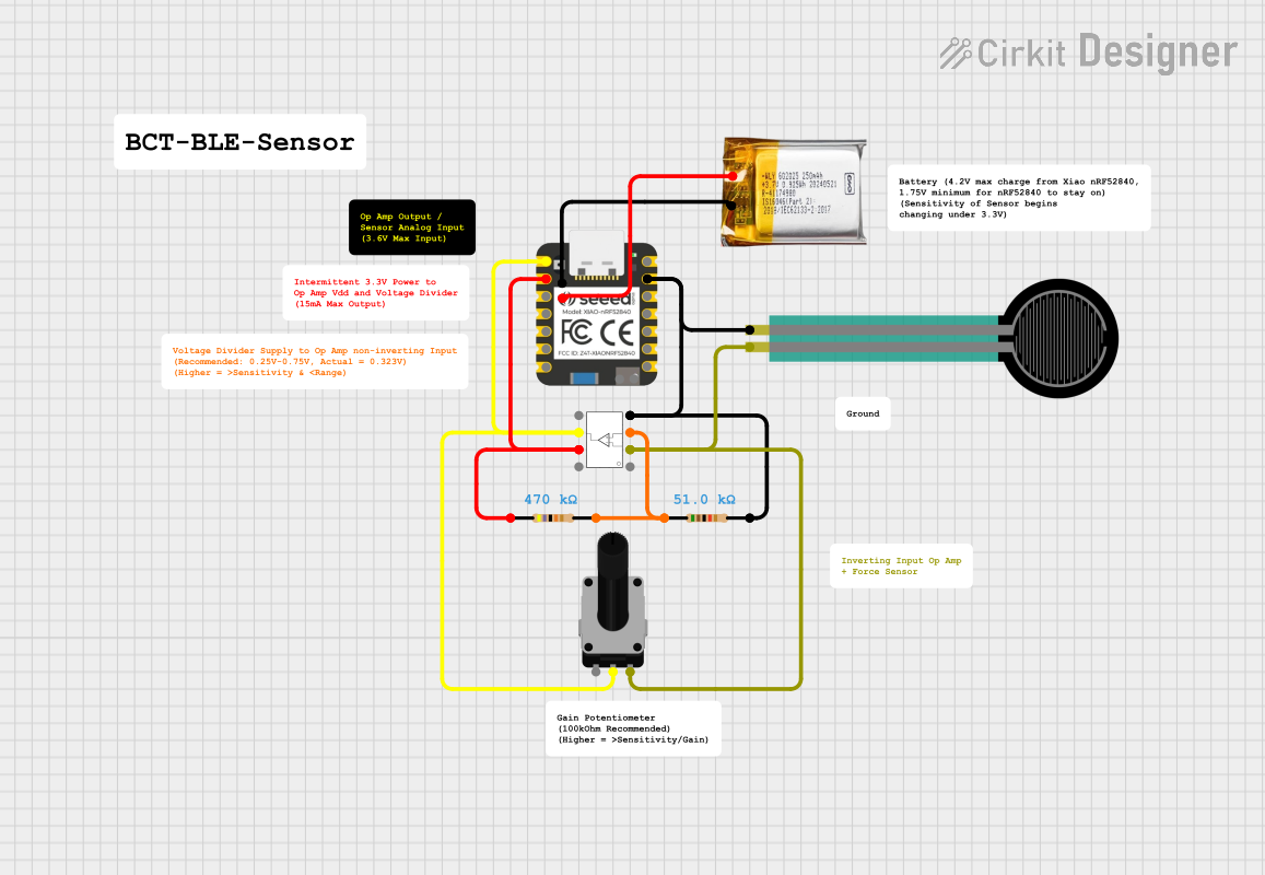
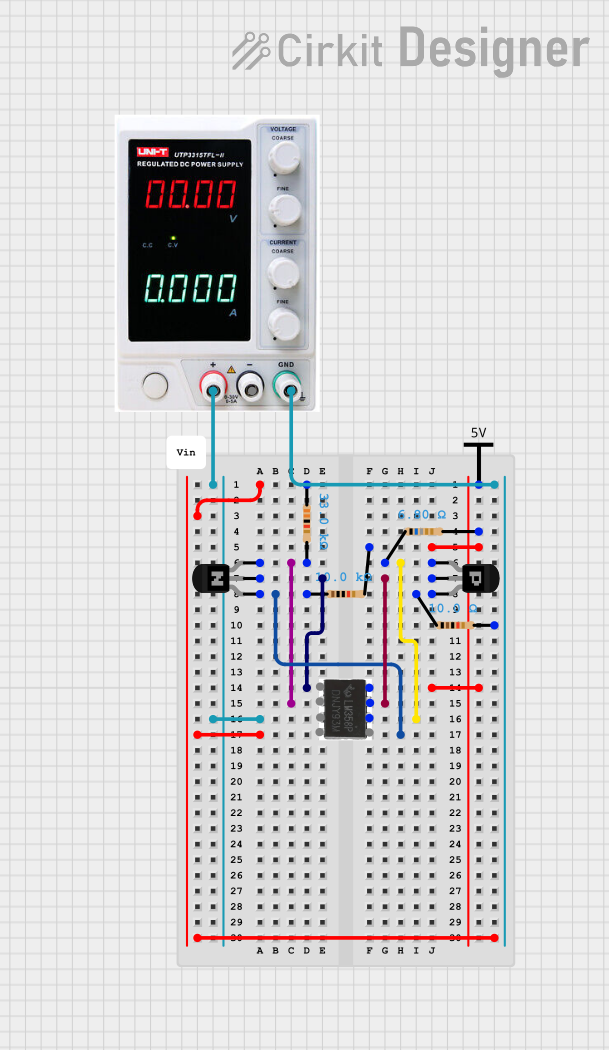

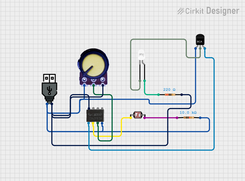
Explore Projects Built with OPA
Common Applications and Use Cases
- Audio amplifiers and preamplifiers
- Active filters and equalizers
- Analog-to-digital converters (ADC) drivers
- Voltage comparators
- Oscillators
- Sensor signal amplification
- Medical instrumentation
Technical Specifications
The OPA series encompasses a range of Op-Amps with varying specifications. Below is a generic table for a typical OPA series Op-Amp. For specific models, refer to the datasheet provided by Texas Instruments.
| Parameter | Value (Typical) | Description |
|---|---|---|
| Supply Voltage (V) | ±2.5 to ±18 | The range of supply voltage the Op-Amp can operate on. |
| Input Offset Voltage (mV) | 0.1 to 3 | The differential input voltage required to make the output voltage zero. |
| Input Bias Current (nA) | 10 to 100 | The current flowing into the input terminals. |
| Gain Bandwidth Product (MHz) | 1 to 100 | The product of the amplifier's bandwidth and its gain. |
| Output Current (mA) | 20 to 50 | The maximum current the Op-Amp can source or sink from its output. |
| Number of Channels | 1 to 4 | The number of independent Op-Amp units in a single package. |
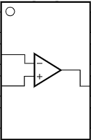
Pin Configuration and Descriptions
For a single-channel OPA series Op-Amp, the pin configuration is typically as follows:
| Pin Number | Name | Description |
|---|---|---|
| 1 | OUT | Output of the Op-Amp. |
| 2 | IN- | Inverting input. |
| 3 | IN+ | Non-inverting input. |
| 4 | V- | Negative power supply. |
| 5 | NC | No connection or offset null (model dependent). |
| 6 | NC | No connection or offset null (model dependent). |
| 7 | V+ | Positive power supply. |
| 8 | NC | No connection (model dependent). |
Note: Pin configurations may vary between different models. Always consult the specific datasheet for accurate information.
Usage Instructions
How to Use the Component in a Circuit
Power Supply: Connect the V+ and V- pins to the positive and negative power supplies, respectively. Ensure that the supply voltage is within the specified range for the Op-Amp model being used.
Input Signals: Apply the signals to be amplified to the IN+ (non-inverting input) and IN- (inverting input) pins. The difference between these signals will be amplified.
Output: The amplified signal can be taken from the OUT pin. The output can be connected to subsequent stages in the circuit or to a load, ensuring it does not exceed the Op-Amp's current rating.
Feedback: To control the gain and bandwidth of the Op-Amp, feedback components such as resistors and capacitors are typically connected between the OUT pin and the IN- pin.
Important Considerations and Best Practices
Decoupling Capacitors: Place decoupling capacitors close to the power supply pins to filter out noise and provide a stable voltage supply.
Bypassing: Use bypass capacitors on the input lines to reduce high-frequency noise.
Heat Dissipation: Ensure proper heat sinking if the Op-Amp is expected to operate at high output currents or if it is dissipating significant power.
Grounding: Maintain a good ground connection to minimize noise and ensure stable operation.
Avoid Oscillations: Layout considerations are crucial to prevent parasitic capacitances that can lead to oscillations. Keep input and output traces separate and use guard rings if necessary.
Troubleshooting and FAQs
Common Issues Users Might Face
Oscillations: If the Op-Amp is oscillating, check the feedback network and layout for stability issues. Adding a compensation capacitor or improving the PCB layout may help.
Output Not Responding: Verify that the power supply is within the specified range and that the input signals are within the input common-mode range.
Excessive Noise: Ensure that the input bias currents are matched and that the power supply lines are properly decoupled.
Solutions and Tips for Troubleshooting
No Output: Check for proper supply voltage and correct pin connections. Ensure that the input signals are within the specified range.
Distorted Output: This could be due to overdriving the inputs or outputs. Check the input and output levels and reduce them if necessary.
Thermal Shutdown: If the Op-Amp shuts down intermittently, it may be entering thermal protection mode. Improve heat dissipation or reduce the power dissipation within the Op-Amp.
FAQs
Q: Can I use the OPA series Op-Amp for a single-supply operation? A: Yes, many OPA series Op-Amps are capable of single-supply operation. Check the datasheet for the specific model to ensure proper functionality.
Q: What is the typical application for an OPA series Op-Amp? A: OPA series Op-Amps are used in a variety of applications, including audio amplification, active filtering, and sensor signal conditioning.
Q: How do I set the gain of the Op-Amp? A: The gain is set by the ratio of the feedback resistor to the input resistor in the feedback network. Consult the datasheet for recommended resistor values and configurations.
For specific code examples and more detailed troubleshooting, please refer to the datasheet and application notes provided by Texas Instruments for the specific OPA series Op-Amp model you are using.