
How to Use RCCB type B: Examples, Pinouts, and Specs
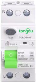
 Design with RCCB type B in Cirkit Designer
Introduction
A Residual Current Circuit Breaker (RCCB) Type B is an advanced safety device designed to detect and disconnect electrical circuits in the presence of residual currents, including alternating current (AC), pulsating direct current (DC), and smooth DC residual currents. Unlike standard RCCBs, Type B devices are specifically engineered to handle DC fault currents, making them ideal for modern electrical systems that include components like solar inverters, electric vehicle (EV) chargers, and variable frequency drives (VFDs).
Explore Projects Built with RCCB type B
 Open Project in Cirkit Designer
 Open Project in Cirkit Designer
 Open Project in Cirkit Designer
 Open Project in Cirkit Designer
Explore Projects Built with RCCB type B
Open Project in Cirkit DesignerOpen Project in Cirkit DesignerOpen Project in Cirkit DesignerOpen Project in Cirkit DesignerCommon Applications and Use Cases
- Electric vehicle (EV) charging stations
- Solar photovoltaic (PV) systems
- Industrial machinery with variable frequency drives (VFDs)
- Uninterruptible power supplies (UPS)
- Medical equipment
- Data centers and IT infrastructure
Technical Specifications
Key Technical Details
- Rated Voltage (Un): 230V AC (single-phase) or 400V AC (three-phase)
- Rated Current (In): 16A, 25A, 40A, 63A, or 100A (varies by model)
- Rated Residual Operating Current (IΔn): 10mA, 30mA, 100mA, 300mA, or 500mA
- Frequency Range: 50Hz/60Hz
- Sensitivity: AC, pulsating DC, and smooth DC residual currents
- Breaking Capacity: 6kA or 10kA (depending on model)
- Operating Temperature Range: -25°C to +40°C
- Standards Compliance: IEC/EN 61008-1, IEC/EN 62423
Pin Configuration and Descriptions
The RCCB Type B typically has four terminals for connection in a single-phase or three-phase system. The table below describes the pin configuration:
| Pin Number | Label | Description |
|---|---|---|
| 1 | L (Line In) | Input terminal for the live wire (phase) |
| 2 | N (Neutral In) | Input terminal for the neutral wire |
| 3 | L (Line Out) | Output terminal for the live wire (phase) |
| 4 | N (Neutral Out) | Output terminal for the neutral wire |
For three-phase RCCBs, additional terminals (L2, L3) are included for the second and third phases.
Usage Instructions
How to Use the RCCB Type B in a Circuit
Determine the System Requirements:
- Identify the rated current (In) and residual operating current (IΔn) suitable for your application.
- Ensure the RCCB Type B is compatible with the voltage and frequency of your system.
Wiring the RCCB:
- Connect the live wire (phase) to the L (Line In) terminal and the neutral wire to the N (Neutral In) terminal.
- Connect the load side wires to the L (Line Out) and N (Neutral Out) terminals.
- For three-phase systems, connect the additional phase wires (L2, L3) to their respective terminals.
Testing the RCCB:
- Use the built-in test button to verify the functionality of the RCCB. Pressing the test button should trip the breaker, indicating proper operation.
Install in a Suitable Enclosure:
- Mount the RCCB in a distribution board or enclosure that provides adequate protection and ventilation.
Important Considerations and Best Practices
- Always ensure the RCCB is installed by a qualified electrician.
- Verify that the RCCB Type B is rated for the maximum fault current of your system.
- Regularly test the RCCB using the test button to ensure it remains functional.
- Avoid overloading the RCCB beyond its rated current (In).
- For EV chargers and solar PV systems, ensure compliance with local electrical codes and standards.
Example: Connecting RCCB Type B to an Arduino-Based Monitoring System
While RCCBs are not directly controlled by microcontrollers like Arduino, you can monitor their status using an auxiliary contact (if available). Below is an example of how to monitor the RCCB's trip status using an Arduino:
// Example code to monitor RCCB trip status using an auxiliary contact
const int rccbStatusPin = 2; // Pin connected to RCCB auxiliary contact
const int ledPin = 13;       // Built-in LED to indicate RCCB status

void setup() {
  pinMode(rccbStatusPin, INPUT_PULLUP); // Configure RCCB status pin as input
  pinMode(ledPin, OUTPUT);              // Configure LED pin as output
  digitalWrite(ledPin, LOW);            // Turn off LED initially
  Serial.begin(9600);                   // Initialize serial communication
}

void loop() {
  int rccbStatus = digitalRead(rccbStatusPin); // Read RCCB status
  if (rccbStatus == HIGH) {
    // RCCB is in normal state (not tripped)
    digitalWrite(ledPin, LOW); // Turn off LED
    Serial.println("RCCB Status: Normal");
  } else {
    // RCCB has tripped
    digitalWrite(ledPin, HIGH); // Turn on LED
    Serial.println("RCCB Status: Tripped");
  }
  delay(500); // Wait for 500ms before next status check
}
Troubleshooting and FAQs
Common Issues and Solutions
RCCB Does Not Trip During Testing:
- Cause: Faulty RCCB or incorrect wiring.
- Solution: Verify the wiring connections and ensure the test button is functional. Replace the RCCB if necessary.
Frequent Tripping of RCCB:
- Cause: Leakage current exceeding the rated residual operating current (IΔn).
- Solution: Inspect the connected devices for insulation faults or excessive leakage current. Use a higher IΔn RCCB if appropriate.
RCCB Trips Without Apparent Faults:
- Cause: Nuisance tripping due to transient currents or harmonics.
- Solution: Ensure the RCCB Type B is suitable for the application. Consider using a time-delay RCCB if transient currents are common.
RCCB Does Not Reset After Tripping:
- Cause: Persistent fault in the circuit.
- Solution: Disconnect all loads and reset the RCCB. Reconnect loads one by one to identify the faulty device.
FAQs
Q1: Can I use an RCCB Type B in a standard residential installation?
A1: Yes, but it is typically over-specified for standard residential installations. RCCB Type B is more suitable for systems with DC fault currents, such as EV chargers or solar PV systems.
Q2: How often should I test the RCCB?
A2: It is recommended to test the RCCB using the test button at least once every six months.
Q3: What is the difference between RCCB Type A and Type B?
A3: RCCB Type A detects AC and pulsating DC residual currents, while Type B can also detect smooth DC residual currents, making it suitable for advanced applications like EV chargers and solar inverters.
Q4: Can an RCCB Type B protect against overcurrent?
A4: No, RCCBs are designed to detect residual currents. For overcurrent protection, use a circuit breaker or an RCBO (Residual Current Breaker with Overcurrent).