How to Use Rotary Encoder: Examples, Pinouts, and Specs
Introduction
A rotary encoder is an electromechanical device that converts the angular position or motion of a shaft or axle to an analog or digital code. Unlike potentiometers, rotary encoders provide full rotation without limits. They are commonly used in applications that require precise control over parameters such as volume, selection, or navigation in user interfaces, as well as in robotics and industrial controls for monitoring movement.
Explore Projects Built with Rotary Encoder
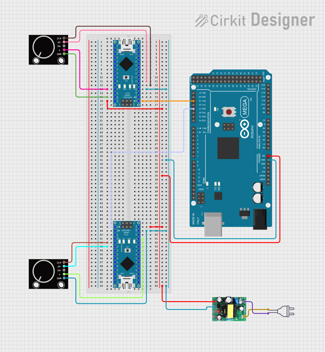
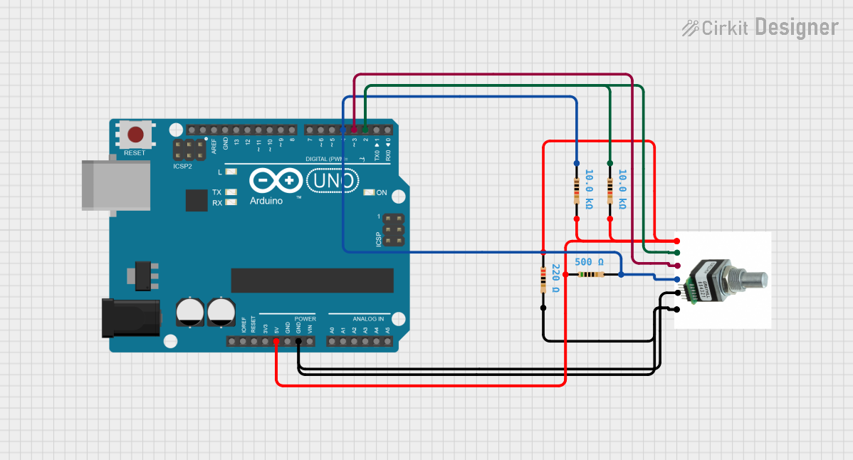
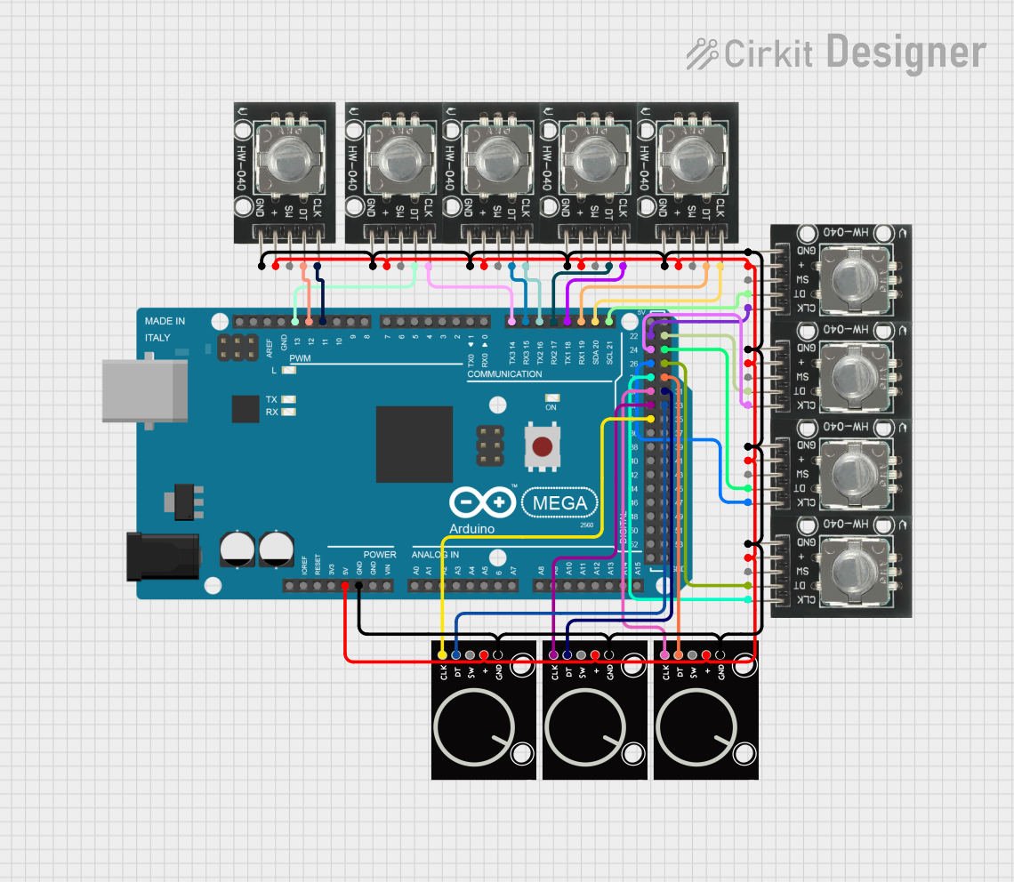
Explore Projects Built with Rotary Encoder
Technical Specifications
Key Technical Details
- Type: Incremental Rotary Encoder
- Output: Digital Quadrature (A and B phase) signals
- Resolution: Typically ranges from 12 to 1024 pulses per revolution (PPR)
- Supply Voltage: 3.3V to 5V
- Maximum Rotational Speed: Varies, often around 6000 RPM
- Operating Temperature: -40°C to +85°C (may vary by model)
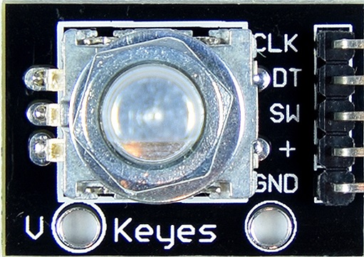
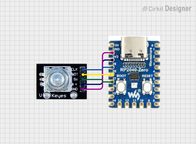
Pin Configuration and Descriptions
| Pin Number | Name | Description |
|---|---|---|
| 1 | Vcc | Power supply (3.3V to 5V) |
| 2 | GND | Ground connection |
| 3 | A | Output A - Quadrature output 1 |
| 4 | B | Output B - Quadrature output 2 |
| 5 | SW | Pushbutton switch (active low, optional) |
Usage Instructions
Connecting to a Circuit
- Connect the Vcc pin to the power supply (3.3V or 5V).
- Connect the GND pin to the ground of the power supply.
- Connect the A and B pins to two digital input pins on a microcontroller, such as an Arduino UNO.
- If available, connect the SW pin to another digital input pin for the pushbutton feature.
Important Considerations and Best Practices
- Use pull-up resistors on the A and B outputs to ensure reliable signal levels, especially in noisy environments.
- Debouncing may be necessary for the pushbutton switch to prevent false triggering from mechanical vibrations.
- When using with a microcontroller, ensure that the encoder's voltage levels are compatible with the microcontroller's logic levels.
- For high-speed applications, consider using interrupt service routines (ISRs) to handle the encoder's output signals.
Example Code for Arduino UNO
// Define the pins connected to the encoder
const int pinA = 2; // Encoder output A
const int pinB = 3; // Encoder output B
const int buttonPin = 4; // Encoder button pin

volatile int encoderPos = 0; // Variable to store the encoder position
bool lastEncoded = LOW; // Last encoded signal from pin A

// Interrupt service routine for encoder A change
void doEncoderA(){
  bool currentEncoded = digitalRead(pinA);
  if (digitalRead(pinB) != currentEncoded) {
    encoderPos++;
  } else {
    encoderPos--;
  }
  lastEncoded = currentEncoded;
}

// Interrupt service routine for encoder B change
void doEncoderB(){
  bool currentEncoded = digitalRead(pinA);
  if (digitalRead(pinB) == currentEncoded) {
    encoderPos++;
  } else {
    encoderPos--;
  }
}

void setup() {
  pinMode(pinA, INPUT);
  pinMode(pinB, INPUT);
  pinMode(buttonPin, INPUT_PULLUP); // Enable internal pull-up

  // Attach the interrupt service routines to the encoder pins
  attachInterrupt(digitalPinToInterrupt(pinA), doEncoderA, CHANGE);
  attachInterrupt(digitalPinToInterrupt(pinB), doEncoderB, CHANGE);
}

void loop() {
  // The main program can read encoderPos to determine the current position
  // or use the button state for additional functionality.
}
Troubleshooting and FAQs
Common Issues
- Erratic Behavior: If the encoder output is erratic, check for proper debouncing and ensure that pull-up resistors are in place.
- No Response: Verify that the encoder is powered correctly and that the pins are connected to the correct microcontroller pins.
- Inaccurate Positioning: Ensure that the encoder's PPR is correctly accounted for in the code and that interrupts are properly handled.
Solutions and Tips for Troubleshooting
- Debouncing: Implement software debouncing in the interrupt routines or use hardware debouncing circuits.
- Pull-Up Resistors: If not using internal pull-ups, add external pull-up resistors (typically 10kΩ) to the A and B outputs.
- Check Connections: Revisit all connections and solder joints for any loose or cold solder points.
FAQs
Q: Can I use a rotary encoder for continuous rotation? A: Yes, rotary encoders are designed for continuous rotation without limits.
Q: How do I determine the direction of rotation? A: The direction can be determined by the sequence of the A and B outputs. If A leads B, for instance, the encoder is rotating in one direction; if B leads A, it's the opposite direction.
Q: What is the purpose of the SW pin? A: The SW pin is connected to a pushbutton switch built into the encoder. It can be used as a select button or for any other input purpose.
Q: How do I increase the resolution of my encoder? A: The resolution is fixed based on the encoder's design. To achieve higher resolution, you would need to use an encoder with a higher PPR specification.