How to Use Buzzer Passive: Examples, Pinouts, and Specs
Introduction
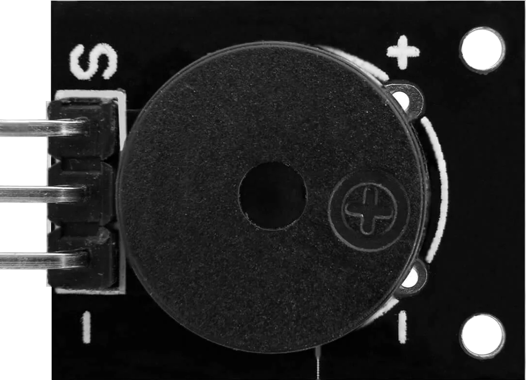
The AZDelivery KY-006 Passive Buzzer is an electronic component designed to produce sound when an alternating current (AC) signal is applied. Unlike an active buzzer, which generates sound internally, the passive buzzer requires an external signal to produce tones of varying frequencies. This makes it ideal for applications where precise control over sound frequency and duration is required.
Explore Projects Built with Buzzer Passive
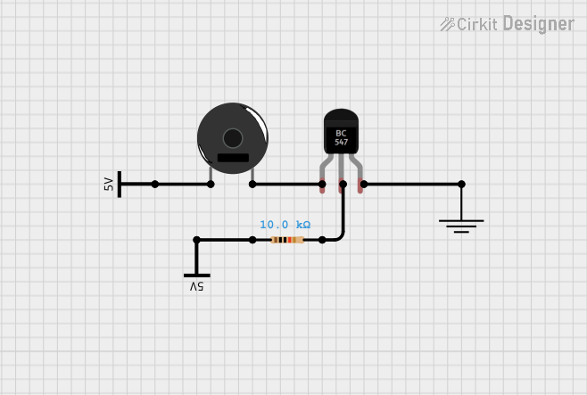
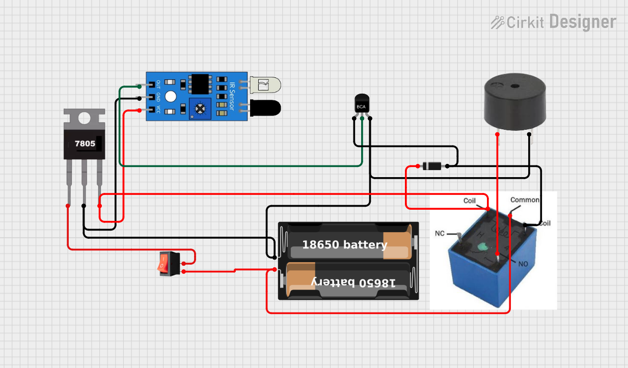
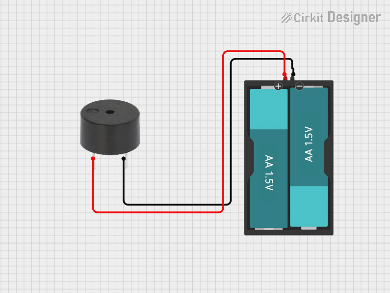
Explore Projects Built with Buzzer Passive
Common Applications
- Alarms and notifications
- Timers and reminders
- Sound effects in electronic projects
- Educational and hobbyist projects
- Arduino-based sound generation
Technical Specifications
The following table outlines the key technical details of the AZDelivery KY-006 Passive Buzzer:
| Parameter | Value |
|---|---|
| Manufacturer | AZDelivery |
| Part ID | KY-006 |
| Operating Voltage | 3.3V to 5V |
| Operating Current | ≤ 30mA |
| Frequency Range | 1kHz to 10kHz (input signal) |
| Dimensions | 18mm x 11mm x 8mm |
| Weight | ~2g |
Pin Configuration
The KY-006 Passive Buzzer module has three pins, as described in the table below:
| Pin | Label | Description |
|---|---|---|
| 1 | Signal | Input pin for the AC signal to generate sound. |
| 2 | VCC | Positive power supply pin (3.3V to 5V). |
| 3 | GND | Ground pin for the power supply. |
Usage Instructions
How to Use the KY-006 Passive Buzzer in a Circuit
- Power Supply: Connect the VCC pin to a 3.3V or 5V power source and the GND pin to the ground.
- Signal Input: Use a microcontroller (e.g., Arduino UNO) or an external oscillator to provide an AC signal to the Signal pin. The frequency of the signal determines the tone of the sound produced.
- Circuit Example: Below is a simple connection diagram for using the KY-006 Passive Buzzer with an Arduino UNO:
- Connect the Signal pin to a digital output pin on the Arduino (e.g., D8).
- Connect the VCC pin to the Arduino's 5V pin.
- Connect the GND pin to the Arduino's GND pin.
Arduino Code Example
The following Arduino code demonstrates how to generate a tone using the KY-006 Passive Buzzer:
// Define the pin connected to the Signal pin of the KY-006 Passive Buzzer
const int buzzerPin = 8;

void setup() {
  // Set the buzzer pin as an output
  pinMode(buzzerPin, OUTPUT);
}

void loop() {
  // Generate a tone at 1000 Hz for 500 milliseconds
  tone(buzzerPin, 1000, 500);
  delay(1000); // Wait for 1 second before the next tone

  // Generate a tone at 2000 Hz for 300 milliseconds
  tone(buzzerPin, 2000, 300);
  delay(700); // Wait for 0.7 seconds before the next tone
}
Important Considerations and Best Practices
- Signal Frequency: Ensure the input signal frequency is within the buzzer's operating range (1kHz to 10kHz) for optimal sound output.
- Power Supply: Use a stable power source to avoid noise or distortion in the sound.
- Volume Control: The volume of the buzzer depends on the amplitude of the input signal. Adjust the signal strength accordingly.
- Avoid DC Signals: Do not apply a constant DC voltage to the Signal pin, as the buzzer will not produce sound.
Troubleshooting and FAQs
Common Issues and Solutions
No Sound Output
Cause: No signal applied to the Signal pin.
Solution: Verify that the microcontroller or oscillator is generating an AC signal.
Cause: Incorrect wiring.
Solution: Double-check the connections to ensure the Signal, VCC, and GND pins are properly connected.
Distorted or Weak Sound
Cause: Signal frequency is outside the buzzer's operating range.
Solution: Adjust the signal frequency to fall within the 1kHz to 10kHz range.
Cause: Insufficient power supply.
Solution: Ensure the power supply provides a stable voltage of 3.3V to 5V.
Buzzer Overheating
- Cause: Excessive current or prolonged use at high signal amplitudes.
- Solution: Limit the signal amplitude and avoid continuous operation for extended periods.
FAQs
Q1: Can I use the KY-006 Passive Buzzer without a microcontroller?
A1: Yes, you can use an external oscillator or signal generator to drive the buzzer. Ensure the signal frequency and amplitude are within the specified range.
Q2: How is the KY-006 Passive Buzzer different from an active buzzer?
A2: The passive buzzer requires an external AC signal to produce sound, while an active buzzer has an internal oscillator and only needs a DC voltage to operate.
Q3: Can I control the volume of the buzzer?
A3: The volume can be adjusted by varying the amplitude of the input signal. However, ensure the amplitude does not exceed the buzzer's maximum rating.
Q4: What happens if I apply a DC voltage to the Signal pin?
A4: The buzzer will not produce sound, as it requires an alternating signal to generate vibrations.
By following this documentation, you can effectively integrate the AZDelivery KY-006 Passive Buzzer into your electronic projects and troubleshoot any issues that arise.