How to Use power supply: Examples, Pinouts, and Specs
Introduction
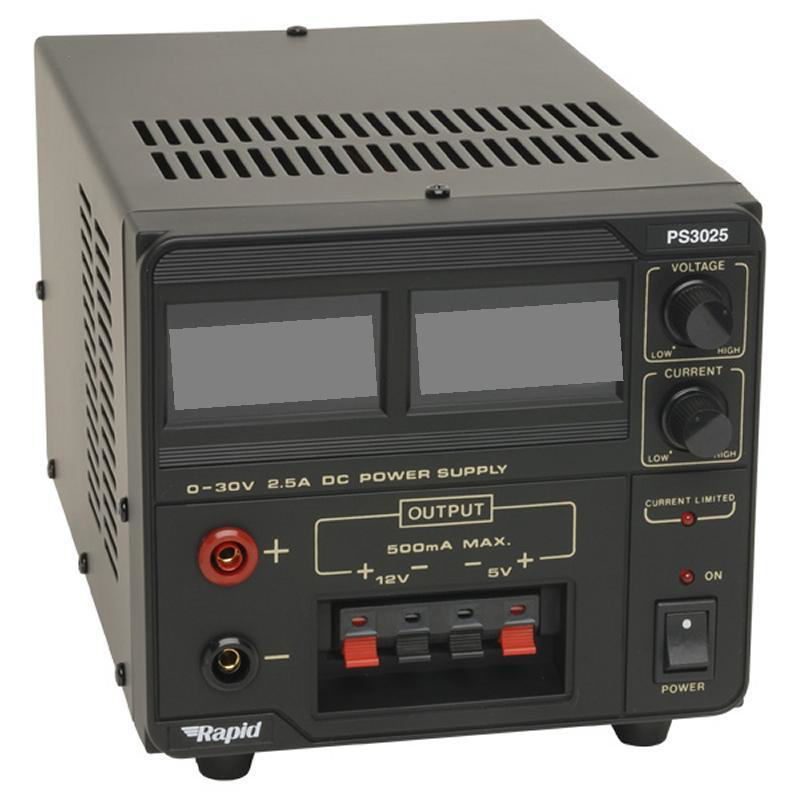
A power supply is a crucial electronic component that provides electrical power to a circuit. It converts and regulates voltage and current to meet the requirements of the components in the circuit. Power supplies are essential in various applications, from simple electronic gadgets to complex industrial systems. They ensure that all components receive the correct voltage and current, thereby ensuring the proper functioning and longevity of the entire system.
Explore Projects Built with power supply


Explore Projects Built with power supply
Common Applications and Use Cases
- Consumer Electronics: Power supplies are used in devices like smartphones, laptops, and televisions.
- Industrial Equipment: They power machinery and control systems in manufacturing plants.
- Medical Devices: Power supplies are critical in medical equipment such as MRI machines and patient monitors.
- Communication Systems: They are used in routers, modems, and other networking devices.
- Automotive: Power supplies are used in car electronics, including infotainment systems and engine control units.
Technical Specifications
Key Technical Details
| Parameter | Value |
|---|---|
| Input Voltage | 100-240V AC |
| Output Voltage | 5V, 12V, 24V DC (varies) |
| Output Current | 0.5A to 10A (varies) |
| Power Rating | 5W to 240W (varies) |
| Efficiency | Up to 90% |
| Ripple and Noise | < 50mV |
| Operating Temp. | -20°C to 70°C |
| Protection | Overload, Short Circuit, OVP |
Pin Configuration and Descriptions
| Pin Number | Pin Name | Description |
|---|---|---|
| 1 | AC_L | AC Live input |
| 2 | AC_N | AC Neutral input |
| 3 | GND | Ground |
| 4 | Vout+ | Positive DC output |
| 5 | Vout- | Negative DC output |
| 6 | Adj | Voltage adjustment (if available) |
Usage Instructions
How to Use the Component in a Circuit
- Identify the Input and Output Pins: Refer to the pin configuration table to identify the AC input pins (AC_L and AC_N) and the DC output pins (Vout+ and Vout-).
- Connect the AC Input: Connect the AC_L and AC_N pins to the AC power source. Ensure that the power source matches the input voltage rating of the power supply.
- Connect the DC Output: Connect the Vout+ and Vout- pins to the load or the circuit that requires power. Ensure that the load matches the output voltage and current ratings of the power supply.
- Adjust the Output Voltage (if applicable): If the power supply has a voltage adjustment pin (Adj), use a small screwdriver to adjust the output voltage to the desired level.
- Power On: Once all connections are secure, power on the AC source. The power supply should now provide the required DC voltage to the load.
Important Considerations and Best Practices
- Check Ratings: Always check the voltage and current ratings of the power supply and ensure they match the requirements of your circuit.
- Proper Ventilation: Ensure that the power supply has adequate ventilation to prevent overheating.
- Secure Connections: Make sure all connections are secure to avoid short circuits or loose connections.
- Use Fuses: Consider using fuses on the input and output sides to protect against overcurrent conditions.
- Isolation: If the power supply is used in a sensitive application, ensure proper isolation between the AC input and DC output.
Troubleshooting and FAQs
Common Issues Users Might Face
No Output Voltage:
- Solution: Check the AC input connections and ensure the power source is active. Verify that the power supply is not in protection mode due to overload or short circuit.
Output Voltage Too Low/High:
- Solution: Adjust the output voltage using the Adj pin (if available). Ensure the load does not exceed the power supply's current rating.
Overheating:
- Solution: Ensure proper ventilation and check for any obstructions. Verify that the power supply is not overloaded.
Noise in Output:
- Solution: Check for proper grounding and minimize the length of output wires. Use capacitors to filter out noise if necessary.
Solutions and Tips for Troubleshooting
- Use a Multimeter: Always use a multimeter to measure the input and output voltages and currents.
- Check for Short Circuits: Inspect the circuit for any short circuits or loose connections.
- Consult the Datasheet: Refer to the power supply's datasheet for detailed specifications and troubleshooting tips.
- Replace Components: If the power supply is faulty, consider replacing it with a new one to avoid further issues.
Example Code for Arduino UNO
If you are using a power supply to power an Arduino UNO, you can use the following code to test the setup:
// Simple Blink Program to Test Power Supply with Arduino UNO

const int ledPin = 13; // Pin connected to the onboard LED

void setup() {
  pinMode(ledPin, OUTPUT); // Set the LED pin as an output
}

void loop() {
  digitalWrite(ledPin, HIGH); // Turn the LED on
  delay(1000); // Wait for 1 second
  digitalWrite(ledPin, LOW); // Turn the LED off
  delay(1000); // Wait for 1 second
}
This code will blink the onboard LED of the Arduino UNO, indicating that the power supply is providing the necessary power to the board.
This documentation provides a comprehensive overview of a power supply, including its technical specifications, usage instructions, and troubleshooting tips. Whether you are a beginner or an experienced user, this guide will help you effectively use a power supply in your electronic projects.