
Cirkit Designer
Your all-in-one circuit design IDE
Home /
Component Documentation
How to Use Header 8: Examples, Pinouts, and Specs
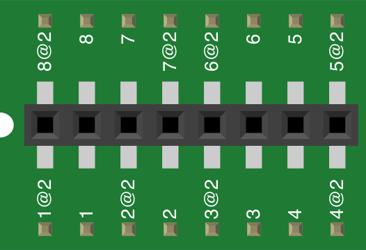
 Design with Header 8 in Cirkit Designer
Introduction
- A Header 8 is a type of connector with 8 pins, typically used for connecting wires or other components in electronic circuits. It allows for easy and secure connections between different parts of a circuit.
- Common applications include prototyping, connecting sensors or modules to microcontrollers, and creating modular circuit designs. Header 8 connectors are widely used in breadboards, PCBs, and Arduino-based projects.
Explore Projects Built with Header 8
Arduino 101 Based Touch-Controlled LED Matrix with DHT22 Sensor Integration
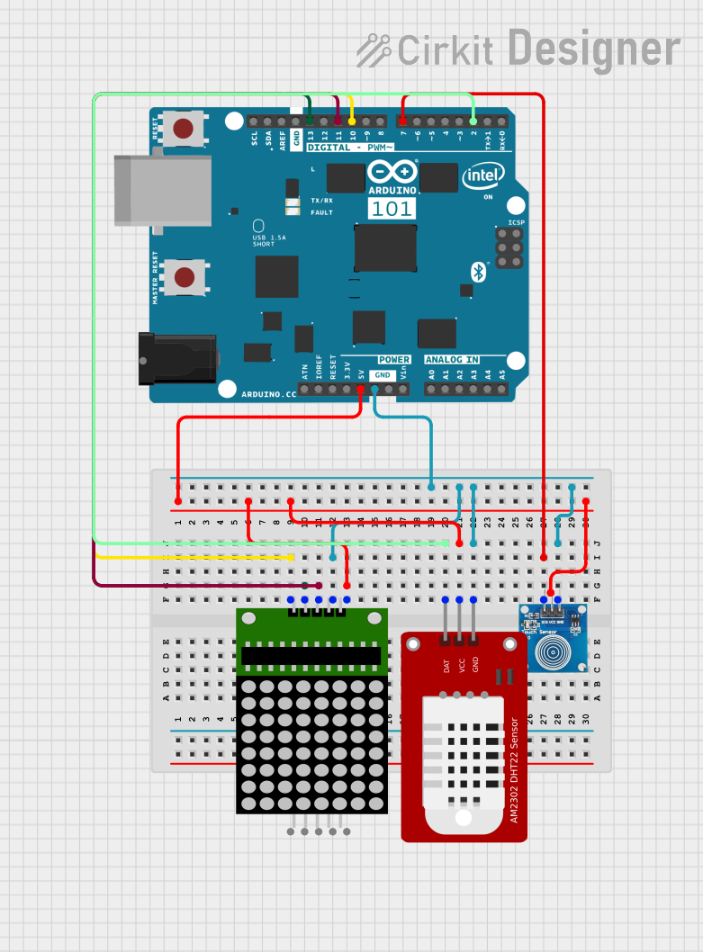
This circuit features an Arduino 101 microcontroller connected to a touch sensor, an 8x8 LED matrix, and a DHT22 temperature and humidity sensor. The Arduino provides power to all components and interfaces with the touch sensor via a digital I/O pin and the DHT22 sensor via another digital I/O pin. It controls the 8x8 LED matrix using SPI communication, with dedicated pins for data, clock, and chip select.
Open Project in Cirkit DesignerArduino UNO Controlled Dual Seven Segment Display with Pushbutton Interaction and AHT10 Temperature Sensor

This circuit features an Arduino UNO microcontroller connected to two seven-segment displays, a pushbutton, a red LED with a 330-ohm resistor, and an AHT10 temperature and humidity sensor. The Arduino controls the segments of the displays via its digital pins and reads the pushbutton state. The LED is used as an indicator, and the AHT10 sensor interfaces with the Arduino over I2C to provide environmental data.
Open Project in Cirkit DesignerESP32-Based NTP Clock with DHT22 Temperature Sensor and WS2812 LED Matrix Display
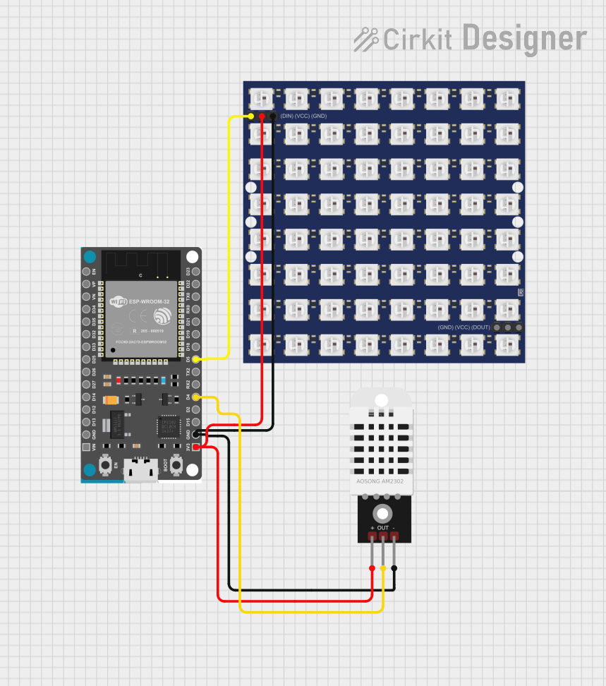
This circuit features an ESP32 Devkit V1 microcontroller connected to a DHT22 temperature and humidity sensor and an 8x8 WS2812 RGB LED matrix. The ESP32 reads temperature data from the DHT22 sensor and displays the current date, time, and temperature on the LED matrix, with date and time synchronized via NTP (Network Time Protocol). The ESP32 provides power to both the DHT22 and the LED matrix and communicates with the DHT22 via GPIO 4 and with the LED matrix via GPIO 5.
Open Project in Cirkit DesignerESP32-Based Environmental Monitoring System with OLED Display
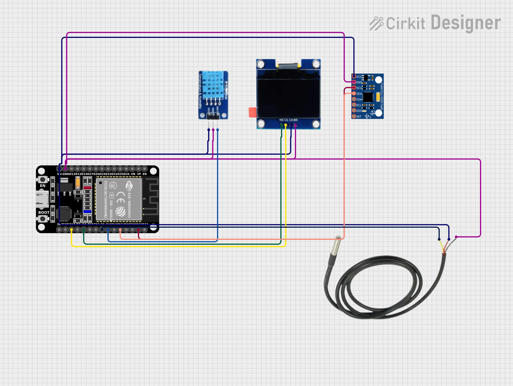
This circuit features an ESP32 microcontroller as the central processing unit, interfacing with a DHT11 temperature and humidity sensor, an MPU-6050 accelerometer and gyroscope, an OLED display, and a separate temperature sensor. The ESP32 communicates with the MPU-6050 and the OLED display via I2C (using pins D22 and D21 for SCL and SDA, respectively), reads temperature data from the DHT11 sensor through pin D18, and interfaces with the additional temperature sensor via pin D5. All components share a common power supply connected to the ESP32's Vin pin and a common ground.
Open Project in Cirkit DesignerExplore Projects Built with Header 8
Arduino 101 Based Touch-Controlled LED Matrix with DHT22 Sensor Integration
This circuit features an Arduino 101 microcontroller connected to a touch sensor, an 8x8 LED matrix, and a DHT22 temperature and humidity sensor. The Arduino provides power to all components and interfaces with the touch sensor via a digital I/O pin and the DHT22 sensor via another digital I/O pin. It controls the 8x8 LED matrix using SPI communication, with dedicated pins for data, clock, and chip select.
Open Project in Cirkit DesignerArduino UNO Controlled Dual Seven Segment Display with Pushbutton Interaction and AHT10 Temperature Sensor
This circuit features an Arduino UNO microcontroller connected to two seven-segment displays, a pushbutton, a red LED with a 330-ohm resistor, and an AHT10 temperature and humidity sensor. The Arduino controls the segments of the displays via its digital pins and reads the pushbutton state. The LED is used as an indicator, and the AHT10 sensor interfaces with the Arduino over I2C to provide environmental data.
Open Project in Cirkit DesignerESP32-Based NTP Clock with DHT22 Temperature Sensor and WS2812 LED Matrix Display
This circuit features an ESP32 Devkit V1 microcontroller connected to a DHT22 temperature and humidity sensor and an 8x8 WS2812 RGB LED matrix. The ESP32 reads temperature data from the DHT22 sensor and displays the current date, time, and temperature on the LED matrix, with date and time synchronized via NTP (Network Time Protocol). The ESP32 provides power to both the DHT22 and the LED matrix and communicates with the DHT22 via GPIO 4 and with the LED matrix via GPIO 5.
Open Project in Cirkit DesignerESP32-Based Environmental Monitoring System with OLED Display
This circuit features an ESP32 microcontroller as the central processing unit, interfacing with a DHT11 temperature and humidity sensor, an MPU-6050 accelerometer and gyroscope, an OLED display, and a separate temperature sensor. The ESP32 communicates with the MPU-6050 and the OLED display via I2C (using pins D22 and D21 for SCL and SDA, respectively), reads temperature data from the DHT11 sensor through pin D18, and interfaces with the additional temperature sensor via pin D5. All components share a common power supply connected to the ESP32's Vin pin and a common ground.
Open Project in Cirkit DesignerTechnical Specifications
- Type: Male or Female Header (8 pins)
- Pin Pitch: 2.54 mm (standard spacing)
- Current Rating: Typically 3A per pin (varies by manufacturer)
- Voltage Rating: Up to 250V (varies by manufacturer)
- Operating Temperature: -40°C to 105°C
- Material:
- Pins: Tin-plated or gold-plated copper alloy
- Housing: Thermoplastic (UL94V-0 rated for flame resistance)
Pin Configuration and Descriptions
The Header 8 does not have a specific pinout since it is a generic connector. However, the table below provides an example of how the pins might be used in a typical application:
| Pin Number | Description | Example Use Case |
|---|---|---|
| 1 | Power (VCC) | Supplies power to a connected device |
| 2 | Ground (GND) | Common ground for the circuit |
| 3 | Signal 1 | Data or control signal |
| 4 | Signal 2 | Data or control signal |
| 5 | Signal 3 | Data or control signal |
| 6 | Signal 4 | Data or control signal |
| 7 | Signal 5 | Data or control signal |
| 8 | Signal 6 | Data or control signal |
Note: The actual pin usage depends on the specific circuit design and application.
Usage Instructions
Connecting the Header 8 to a Circuit:
- Solder the Header 8 onto a PCB or insert it into a breadboard.
- Ensure the pins are aligned correctly with the corresponding connections (e.g., VCC, GND, signals).
- If using a female header, insert the male pins of the connected component into the header.
Important Considerations:
- Verify the pin pitch (2.54 mm) matches the spacing of your PCB or breadboard.
- Avoid exceeding the current and voltage ratings to prevent damage.
- Use heat-resistant tools when soldering to avoid deforming the plastic housing.
Using Header 8 with an Arduino UNO:
- Header 8 connectors are commonly used to connect sensors or modules to the Arduino UNO.
- Example: Connecting a sensor with 6 signal pins and 2 power pins to the Arduino.
Example Code for Arduino UNO
// Example: Reading data from a sensor connected via Header 8

const int sensorPin1 = A0; // Pin 1: Analog input for sensor data
const int sensorPin2 = A1; // Pin 2: Additional sensor input
const int powerPin = 8;    // Pin 3: Power supply to the sensor
const int groundPin = 9;   // Pin 4: Ground connection

void setup() {
  pinMode(powerPin, OUTPUT); // Set power pin as output
  pinMode(groundPin, OUTPUT); // Set ground pin as output
  digitalWrite(powerPin, HIGH); // Turn on power to the sensor
  digitalWrite(groundPin, LOW); // Set ground pin to LOW
  Serial.begin(9600); // Initialize serial communication
}

void loop() {
  int sensorValue1 = analogRead(sensorPin1); // Read data from sensor pin 1
  int sensorValue2 = analogRead(sensorPin2); // Read data from sensor pin 2

  // Print sensor values to the Serial Monitor
  Serial.print("Sensor 1 Value: ");
  Serial.println(sensorValue1);
  Serial.print("Sensor 2 Value: ");
  Serial.println(sensorValue2);

  delay(1000); // Wait for 1 second before reading again
}
Note: Adjust the pin numbers in the code to match your specific circuit design.
Troubleshooting and FAQs
Common Issues
Loose Connections:
- Problem: The connection between the Header 8 and the component is unstable.
- Solution: Ensure the pins are fully inserted and aligned. If soldered, check for cold solder joints and re-solder if necessary.
Overheating During Soldering:
- Problem: The plastic housing melts or deforms during soldering.
- Solution: Use a soldering iron with a temperature control and limit the contact time to a few seconds.
Incorrect Pin Mapping:
- Problem: The circuit does not work as expected due to incorrect pin connections.
- Solution: Double-check the pin mapping and ensure the connections match the circuit design.
FAQs
Q: Can I use a Header 8 with a breadboard?
- A: Yes, Header 8 connectors with a 2.54 mm pitch are compatible with standard breadboards.
Q: What is the difference between male and female Header 8 connectors?
- A: Male headers have exposed pins, while female headers have sockets to receive the pins.
Q: Can I cut a longer header strip to create a Header 8?
- A: Yes, you can cut a longer header strip to the desired length using a sharp tool, but ensure the cut is clean to avoid damaging the pins.
Q: Are Header 8 connectors reusable?
- A: Female headers are reusable, but male headers are typically soldered and may not be easily removed without damage.