How to Use Piezoelectric Tap Shock : Examples, Pinouts, and Specs
Introduction
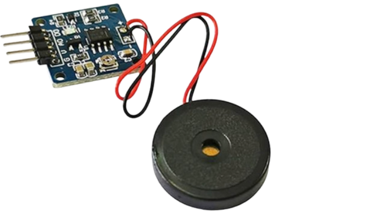
The Piezoelectric Tap Shock is a device that generates an electrical charge when subjected to mechanical stress, such as tapping, vibration, or impact. This component leverages the piezoelectric effect, where certain materials produce an electric charge in response to applied mechanical force. It is widely used in applications requiring motion detection, vibration sensing, or energy harvesting.
Explore Projects Built with Piezoelectric Tap Shock
Explore Projects Built with Piezoelectric Tap Shock
Common Applications and Use Cases
- Vibration Sensors: Detecting vibrations in machinery or structures.
- Impact Detection: Used in touch-sensitive devices or shock detection systems.
- Energy Harvesting: Converting mechanical energy into electrical energy for low-power devices.
- Musical Instruments: Capturing vibrations in acoustic instruments for amplification.
- Wearable Devices: Monitoring motion or impacts in fitness trackers and health monitors.
Technical Specifications
Below are the key technical details of the Piezoelectric Tap Shock component:
| Parameter | Value |
|---|---|
| Operating Voltage | 3.3V to 5V (typical for interfacing) |
| Output Voltage Range | Up to ±90V (depending on impact) |
| Output Signal Type | AC voltage (requires rectification for DC) |
| Sensitivity | High (varies with material and design) |
| Operating Temperature | -20°C to 70°C |
| Dimensions | Varies (commonly small and compact) |
| Material | Piezoelectric ceramic or polymer |
Pin Configuration and Descriptions
The Piezoelectric Tap Shock typically has two terminals:
| Pin | Description |
|---|---|
| Positive (+) | Connects to the input of the circuit or microcontroller. |
| Negative (-) | Connects to ground (GND). |
Usage Instructions
How to Use the Component in a Circuit
Basic Connection:
- Connect the positive terminal of the Piezoelectric Tap Shock to the input pin of your circuit or microcontroller.
- Connect the negative terminal to the ground (GND).
- Since the output is an AC signal, you may need a rectifier circuit if DC voltage is required.
Interfacing with a Microcontroller:
- Use a resistor (e.g., 1MΩ) in parallel with the Piezoelectric Tap Shock to stabilize the signal.
- Optionally, add a capacitor to filter noise.
- Connect the output to an analog input pin of a microcontroller (e.g., Arduino UNO).
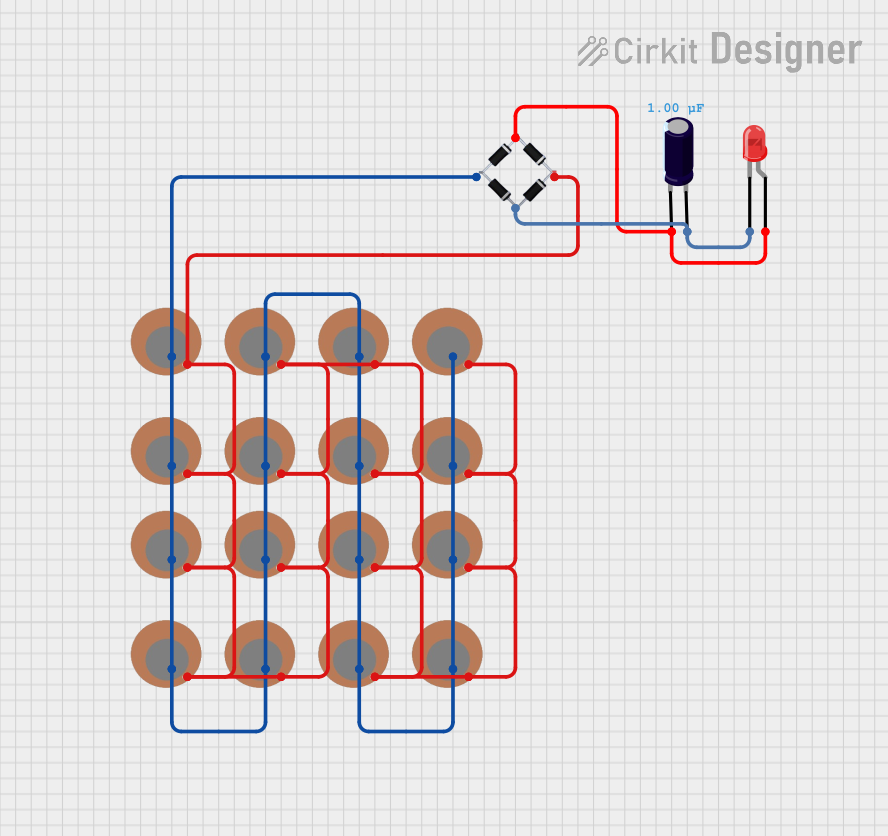
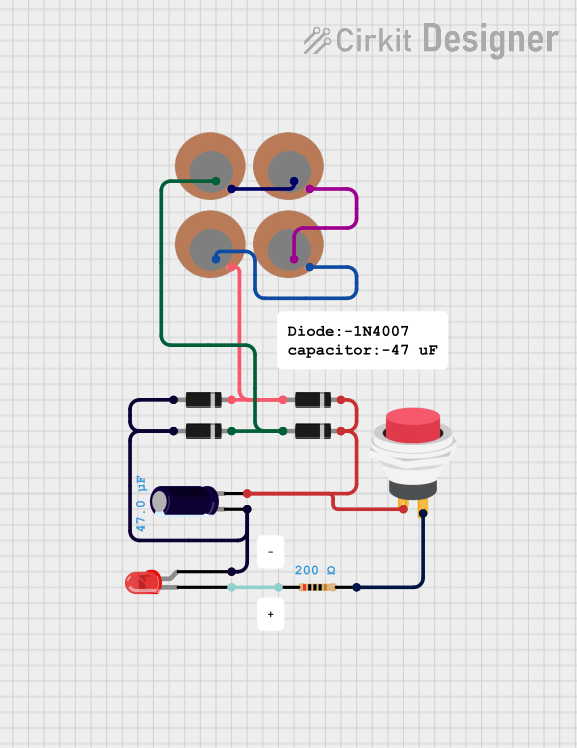
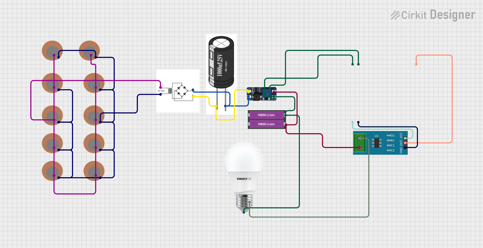
Energy Harvesting:
- Use a rectifier circuit (e.g., a diode bridge) to convert the AC output to DC.
- Add a capacitor to store the harvested energy.
Important Considerations and Best Practices
- Signal Conditioning: The output signal is typically weak and may require amplification for certain applications.
- Voltage Spikes: The component can generate high voltage spikes; use protective components (e.g., diodes) to prevent damage to sensitive circuits.
- Mounting: Ensure the component is securely mounted to avoid false signals due to unintended vibrations.
- Polarity: Observe correct polarity when connecting the component to a circuit.
Example: Interfacing with Arduino UNO
Below is an example of how to use the Piezoelectric Tap Shock with an Arduino UNO to detect taps:
// Piezoelectric Tap Shock Example with Arduino UNO
// This code reads the analog signal from the Piezoelectric Tap Shock
// and prints the detected voltage to the Serial Monitor.

const int piezoPin = A0; // Connect the positive terminal to analog pin A0
int sensorValue = 0;     // Variable to store the sensor reading

void setup() {
  Serial.begin(9600); // Initialize serial communication at 9600 baud
}

void loop() {
  sensorValue = analogRead(piezoPin); // Read the analog value from the sensor
  Serial.println(sensorValue);       // Print the value to the Serial Monitor

  // Add a small delay to avoid flooding the Serial Monitor
  delay(100);
}
Notes:
- Use a 1MΩ resistor in parallel with the Piezoelectric Tap Shock to stabilize the signal.
- Adjust the
delay()value as needed for your application.
Troubleshooting and FAQs
Common Issues and Solutions
No Output Signal:
- Ensure the component is securely connected to the circuit.
- Verify that the mechanical stress (e.g., tapping) is sufficient to generate a signal.
- Check for loose or broken wires.
Weak Signal:
- Use an amplifier circuit to boost the output signal.
- Ensure the resistor and capacitor values are appropriate for your application.
High Voltage Spikes Damaging Circuit:
- Add a Zener diode or TVS diode to clamp voltage spikes.
- Use a voltage divider to reduce the signal amplitude.
Noise in Output Signal:
- Add a capacitor in parallel with the output to filter high-frequency noise.
- Ensure the component is not exposed to unintended vibrations.
FAQs
Q: Can the Piezoelectric Tap Shock be used for energy harvesting?
A: Yes, it can convert mechanical energy into electrical energy. However, the output is typically small and may require a rectifier and capacitor for storage.
Q: How do I measure the output voltage?
A: Use an oscilloscope or a multimeter in AC voltage mode. For DC measurements, use a rectifier circuit.
Q: Can I use this component with a digital input pin?
A: Yes, but you may need to condition the signal (e.g., using a comparator) to ensure it meets the digital input threshold.
Q: Is the component polarity-sensitive?
A: Yes, ensure the positive and negative terminals are connected correctly to avoid incorrect readings.
This concludes the documentation for the Piezoelectric Tap Shock.