
How to Use 12V delay relay module: Examples, Pinouts, and Specs
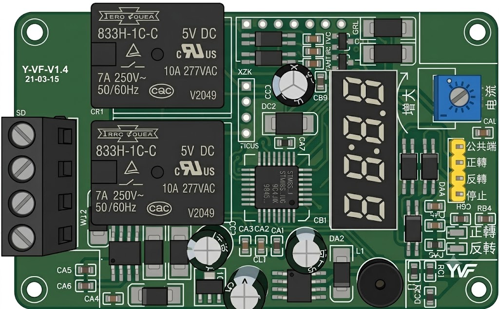
 Design with 12V delay relay module in Cirkit Designer
Introduction
The 12V delay relay module is an electronic component designed to control high-voltage devices using a low-voltage signal. It features a built-in delay function, allowing users to specify a time interval before the relay activates or deactivates. This makes it ideal for applications requiring timed control, such as automation systems, lighting control, motor control, and other time-sensitive operations.
Common applications include:
- Home automation systems
- Industrial equipment control
- Timed motor or pump activation
- Sequential lighting systems
- Security systems with delayed triggers
Explore Projects Built with 12V delay relay module
 Open Project in Cirkit Designer
 Open Project in Cirkit Designer
 Open Project in Cirkit Designer
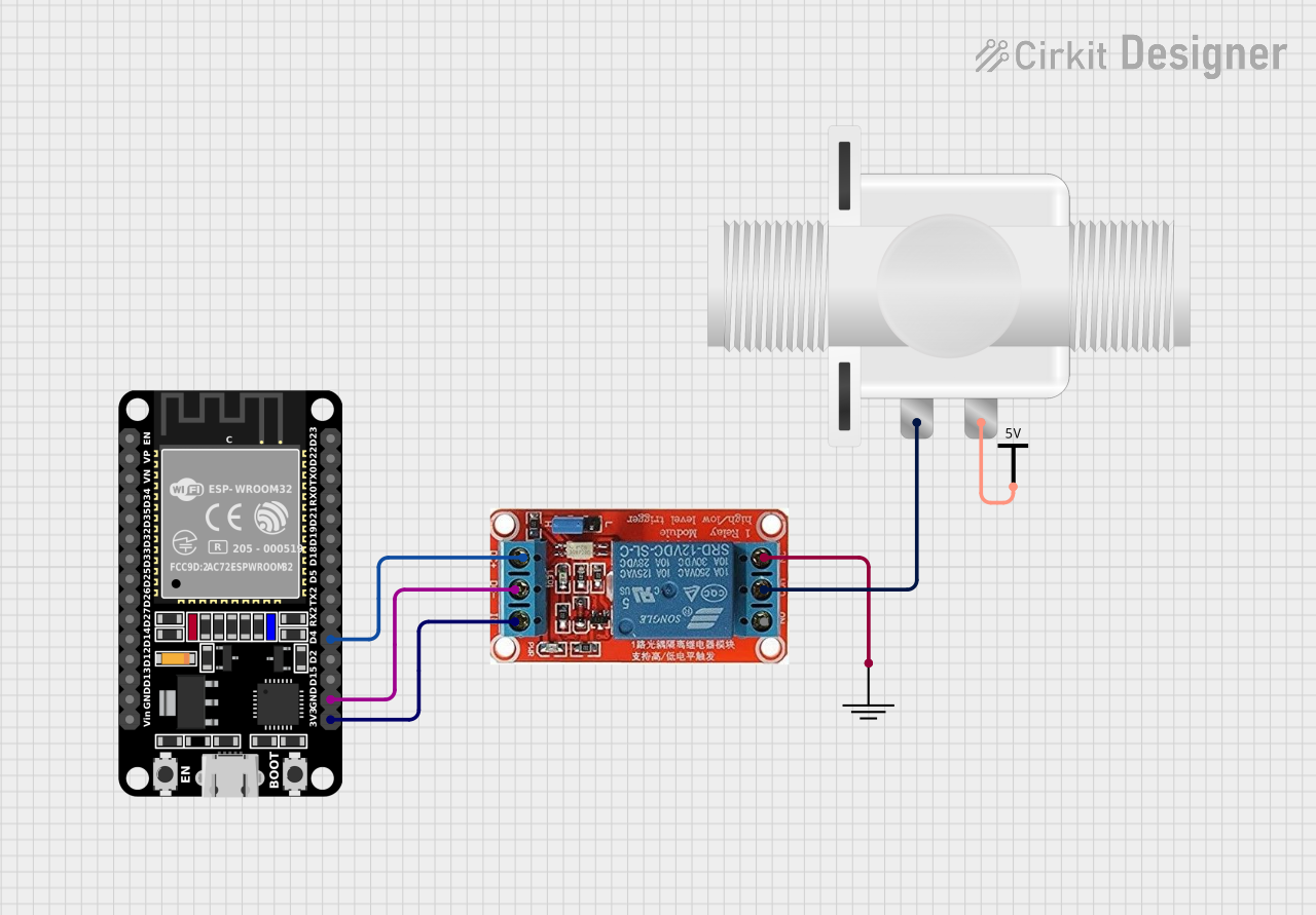 Open Project in Cirkit Designer
Explore Projects Built with 12V delay relay module
Open Project in Cirkit DesignerOpen Project in Cirkit DesignerOpen Project in Cirkit DesignerOpen Project in Cirkit DesignerTechnical Specifications
The following table outlines the key technical details of the 12V delay relay module:
| Parameter | Specification |
|---|---|
| Operating Voltage | 12V DC |
| Trigger Voltage | 3V–12V DC |
| Relay Type | SPDT (Single Pole Double Throw) |
| Maximum Load Voltage | 250V AC / 30V DC |
| Maximum Load Current | 10A |
| Delay Time Range | Adjustable (typically 0–10 seconds) |
| Module Dimensions | Varies by model (e.g., 50mm x 26mm) |
| Power Consumption | < 1W |
| Operating Temperature | -40°C to 85°C |
Pin Configuration and Descriptions
The module typically has the following pin configuration:
Input Pins
| Pin Name | Description |
|---|---|
| VCC | Connect to 12V DC power supply |
| GND | Ground connection |
| IN | Trigger input (low-voltage signal to activate) |
Output Terminals
| Terminal Name | Description |
|---|---|
| NO (Normally Open) | Connect to the load; closes when relay is active |
| COM (Common) | Common terminal for the load connection |
| NC (Normally Closed) | Connect to the load; opens when relay is active |
Usage Instructions
How to Use the Component in a Circuit
- Power the Module: Connect the VCC pin to a 12V DC power supply and the GND pin to ground.
- Connect the Load:
- For devices that should activate when the relay is triggered, connect the load between the NO (Normally Open) terminal and COM (Common) terminal.
- For devices that should deactivate when the relay is triggered, connect the load between the NC (Normally Closed) terminal and COM terminal.
- Set the Delay: Adjust the potentiometer on the module to set the desired delay time. Turning the potentiometer clockwise typically increases the delay, while turning it counterclockwise decreases it.
- Trigger the Relay: Apply a low-voltage signal (3V–12V DC) to the IN pin to activate the relay after the specified delay.
Important Considerations and Best Practices
- Power Supply: Ensure the power supply provides a stable 12V DC to avoid erratic behavior.
- Load Ratings: Do not exceed the maximum load voltage (250V AC / 30V DC) or current (10A) to prevent damage to the relay.
- Isolation: The relay provides electrical isolation between the low-voltage control circuit and the high-voltage load. However, ensure proper insulation and safety precautions when working with high voltages.
- Delay Adjustment: Test the delay time after adjusting the potentiometer to ensure it meets your requirements.
- Arduino Compatibility: The module can be easily interfaced with an Arduino UNO or similar microcontroller for automated control.
Example Arduino Code
// Example code to control a 12V delay relay module with an Arduino UNO
// This code triggers the relay for 5 seconds after a delay of 2 seconds.

#define RELAY_PIN 7  // Define the Arduino pin connected to the relay module

void setup() {
  pinMode(RELAY_PIN, OUTPUT);  // Set the relay pin as an output
  digitalWrite(RELAY_PIN, LOW);  // Ensure the relay is off at startup
}

void loop() {
  delay(2000);  // Wait for 2 seconds (simulate delay before activation)
  digitalWrite(RELAY_PIN, HIGH);  // Activate the relay
  delay(5000);  // Keep the relay active for 5 seconds
  digitalWrite(RELAY_PIN, LOW);  // Deactivate the relay
  delay(10000);  // Wait for 10 seconds before repeating the cycle
}
Troubleshooting and FAQs
Common Issues and Solutions
Relay Does Not Activate:
- Ensure the power supply is providing a stable 12V DC.
- Verify the trigger voltage (3V–12V DC) is applied to the IN pin.
- Check the potentiometer setting; the delay time may be too long.
Erratic Behavior:
- Check for loose connections or unstable power supply.
- Ensure the load does not exceed the relay's maximum ratings.
No Delay Observed:
- Verify the potentiometer is not set to the minimum delay position.
- Test the module with a different load or trigger signal.
Overheating:
- Ensure the load current does not exceed 10A.
- Provide adequate ventilation around the module.
FAQs
Q: Can I use this module with a 5V power supply?
A: No, the module requires a 12V DC power supply for proper operation. However, the trigger signal can range from 3V to 12V DC.
Q: How do I increase the delay time beyond 10 seconds?
A: Some modules allow for delay time extension by replacing the onboard timing capacitor or using an external timing circuit. Refer to the module's datasheet for details.
Q: Is the relay module safe for high-voltage applications?
A: Yes, the relay provides electrical isolation between the control and load circuits. However, always follow proper safety precautions when working with high voltages.
Q: Can I control the relay with a microcontroller?
A: Yes, the module is compatible with microcontrollers like Arduino, Raspberry Pi, and others. Ensure the trigger signal voltage matches the module's input requirements.
By following this documentation, you can effectively integrate the 12V delay relay module into your projects and troubleshoot common issues with ease.