How to Use INA 114: Examples, Pinouts, and Specs
Introduction
The INA114 is a precision instrumentation amplifier manufactured by Texas Instruments (Part ID: IC). It is designed for low-level signal amplification, offering high input impedance, low offset voltage, and low noise. These features make it an excellent choice for applications requiring accurate and stable signal processing. Common use cases include medical instrumentation, sensor signal conditioning, and data acquisition systems.
Explore Projects Built with INA 114

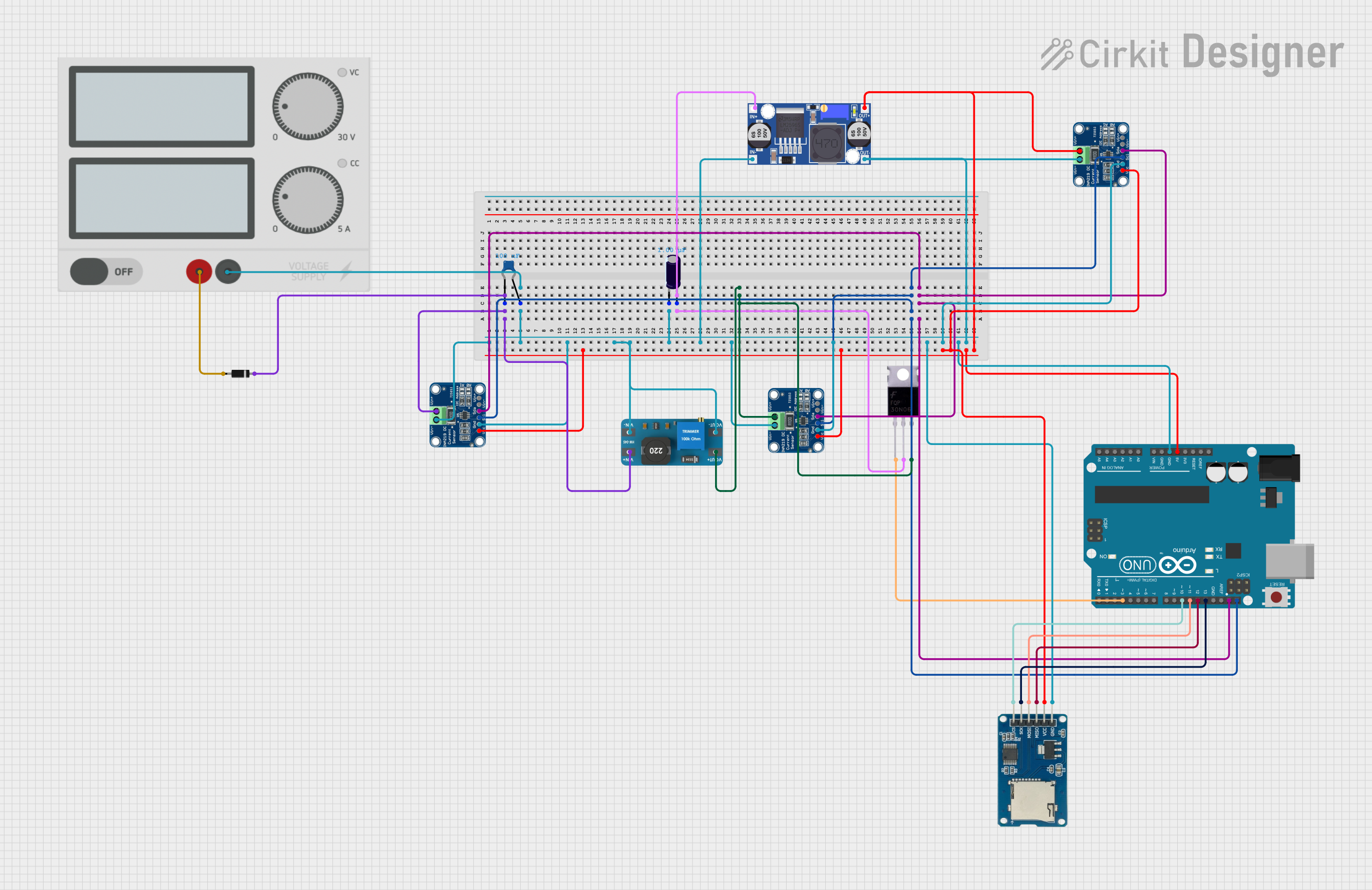
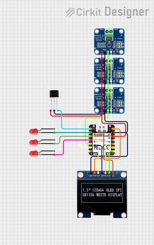
Explore Projects Built with INA 114
Technical Specifications
The INA114 is a high-performance component with the following key specifications:
| Parameter | Value |
|---|---|
| Supply Voltage Range | ±2.25V to ±18V |
| Input Impedance | 10⁹ Ω (typical) |
| Gain Range | 1 to 10,000 (set by external resistor) |
| Offset Voltage | 50 µV (typical) |
| Input Bias Current | 2 nA (typical) |
| Bandwidth | 1 MHz (at G = 1) |
| Slew Rate | 0.3 V/µs |
| Noise | 8 nV/√Hz (at 1 kHz) |
| Operating Temperature Range | -40°C to +85°C |
Pin Configuration and Descriptions
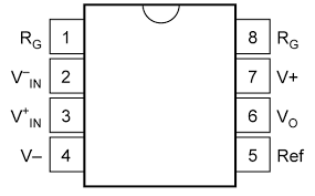
The INA114 is available in an 8-pin DIP or SOIC package. The pinout is as follows:
| Pin Number | Pin Name | Description |
|---|---|---|
| 1 | RG | Gain Resistor Connection (sets gain with external resistor) |
| 2 | -IN | Inverting Input |
| 3 | +IN | Non-Inverting Input |
| 4 | -V (V-) | Negative Power Supply |
| 5 | Ref | Reference Voltage Input (sets output reference level) |
| 6 | Output | Amplifier Output |
| 7 | +V (V+) | Positive Power Supply |
| 8 | RG | Gain Resistor Connection (sets gain with external resistor) |
Usage Instructions
How to Use the INA114 in a Circuit
- Power Supply: Connect the INA114 to a dual power supply (e.g., ±15V) or a single supply (e.g., 5V and ground). Ensure the supply voltage is within the specified range (±2.25V to ±18V).
- Input Connections: Connect the signal source to the +IN (pin 3) and -IN (pin 2) pins. The high input impedance ensures minimal loading on the signal source.
- Gain Setting: Use an external resistor between the RG pins (pins 1 and 8) to set the desired gain. The gain is calculated as: [ G = 1 + \frac{50kΩ}{R_G} ] For example, if ( R_G = 10kΩ ), the gain will be ( G = 6 ).
- Reference Voltage: Connect the Ref pin (pin 5) to ground for a single-ended output. Alternatively, apply a reference voltage to shift the output level.
- Output: The amplified signal is available at the Output pin (pin 6). Connect this pin to the next stage of your circuit.
Important Considerations and Best Practices
- Use precision resistors for the gain-setting resistor ( R_G ) to ensure accurate and stable gain.
- Decouple the power supply with capacitors (e.g., 0.1 µF ceramic and 10 µF electrolytic) close to the power pins to minimize noise.
- Avoid exceeding the input voltage range to prevent distortion or damage to the amplifier.
- For optimal performance, keep the layout clean and minimize the length of input and output traces to reduce noise pickup.
Example: Connecting the INA114 to an Arduino UNO
The INA114 can be used to amplify low-level signals (e.g., from a sensor) for input to an Arduino UNO's analog pin. Below is an example circuit and code:
Circuit Description
- Connect the sensor's output to the +IN pin (pin 3) of the INA114.
- Connect the -IN pin (pin 2) to ground or a reference voltage.
- Use a resistor between RG pins (pins 1 and 8) to set the gain.
- Connect the Output pin (pin 6) to an analog input pin (e.g., A0) of the Arduino UNO.
- Power the INA114 with a ±5V supply or a single 5V supply.
Arduino Code
// INA114 Amplifier Example with Arduino UNO
// Reads the amplified signal from the INA114 and displays it on the Serial Monitor.

const int analogPin = A0; // Analog pin connected to INA114 output
int sensorValue = 0;      // Variable to store the analog reading

void setup() {
  Serial.begin(9600); // Initialize serial communication at 9600 baud
}

void loop() {
  sensorValue = analogRead(analogPin); // Read the analog value
  float voltage = sensorValue * (5.0 / 1023.0); // Convert to voltage
  Serial.print("Amplified Voltage: ");
  Serial.print(voltage);
  Serial.println(" V");
  delay(500); // Wait for 500 ms before the next reading
}
Troubleshooting and FAQs
Common Issues and Solutions
No Output Signal:
- Verify the power supply connections and ensure the voltage is within the specified range.
- Check the input signal and ensure it is within the input voltage range of the INA114.
- Confirm that the gain-setting resistor ( R_G ) is properly connected.
Output Signal is Distorted:
- Ensure the input signal amplitude does not exceed the common-mode input range.
- Check for proper decoupling of the power supply to reduce noise.
Incorrect Gain:
- Verify the value of the gain-setting resistor ( R_G ).
- Use precision resistors to minimize errors.
High Noise in Output:
- Minimize the length of input and output traces to reduce noise pickup.
- Use shielded cables for the input signal if operating in a noisy environment.
FAQs
Q: Can the INA114 operate with a single power supply?
A: Yes, the INA114 can operate with a single supply (e.g., 5V and ground). However, ensure the input and output signals remain within the specified voltage range.
Q: How do I calculate the gain for a specific application?
A: Use the formula ( G = 1 + \frac{50kΩ}{R_G} ), where ( R_G ) is the external resistor connected between pins 1 and 8.
Q: What is the maximum input signal the INA114 can handle?
A: The input signal must remain within the common-mode input range, which depends on the supply voltage. Refer to the datasheet for detailed limits.
Q: Can I use the INA114 for differential signal amplification?
A: Yes, the INA114 is designed for differential signal amplification. Connect the differential signal to the +IN and -IN pins.
By following this documentation, users can effectively integrate the INA114 into their designs for precise and reliable signal amplification.