How to Use TM1621: Examples, Pinouts, and Specs
Introduction
The TM1621 is a low-power, 16-segment LCD driver manufactured by Shenzhen Titan Micro Electronics. It is designed to drive LCD displays with high efficiency and minimal power consumption. The component features a serial interface for seamless communication with microcontrollers, making it ideal for applications requiring compact and energy-efficient display solutions.
Explore Projects Built with TM1621


Explore Projects Built with TM1621
Common Applications
- Digital clocks and timers
- Consumer electronics with LCD displays
- Industrial control panels
- Home appliances
- Handheld devices
Technical Specifications
The TM1621 is a versatile LCD driver with the following key specifications:
| Parameter | Value |
|---|---|
| Operating Voltage (VDD) | 2.4V to 5.5V |
| Operating Current | < 10 µA (typical, at 3V) |
| LCD Drive Voltage (VLCD) | Up to 6.0V |
| Maximum Segment Outputs | 16 segments |
| Maximum Common Outputs | 4 commons |
| Communication Interface | Serial (3-wire) |
| Oscillator | Internal or external (selectable) |
| Operating Temperature | -40°C to +85°C |
| Package | SOP-28, DIP-28 |
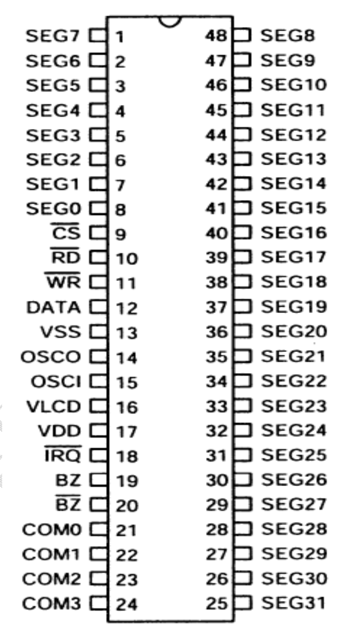
Pin Configuration
The TM1621 has 28 pins, with the following configuration:
| Pin Number | Pin Name | Description |
|---|---|---|
| 1-16 | SEG1-SEG16 | Segment output pins for driving LCD segments |
| 17-20 | COM1-COM4 | Common output pins for driving LCD commons |
| 21 | VDD | Positive power supply |
| 22 | VSS | Ground |
| 23 | VLCD | LCD drive voltage input |
| 24 | OSC | Oscillator input (external clock or resistor) |
| 25 | CS | Chip select for serial communication |
| 26 | WR | Write clock for serial communication |
| 27 | DATA | Data input for serial communication |
| 28 | TEST | Test pin (leave unconnected in normal operation) |
Usage Instructions
Connecting the TM1621 to a Microcontroller
To use the TM1621 in a circuit, follow these steps:
- Power Supply: Connect the VDD pin to a 3.3V or 5V power source and the VSS pin to ground.
- LCD Connections: Connect the SEG1-SEG16 pins to the segment electrodes of the LCD and the COM1-COM4 pins to the common electrodes.
- Oscillator: If using an external clock, connect a resistor or clock signal to the OSC pin. Otherwise, leave it unconnected to use the internal oscillator.
- Serial Communication: Connect the CS, WR, and DATA pins to the corresponding pins on the microcontroller.
- VLCD: Provide the appropriate LCD drive voltage to the VLCD pin.
Example Code for Arduino UNO
Below is an example of how to interface the TM1621 with an Arduino UNO to control an LCD display:
// TM1621 LCD Driver Example Code for Arduino UNO
// Author: Shenzhen Titan Micro Electronics
// Description: This code demonstrates basic communication with the TM1621.

#define TM1621_CS 10   // Chip Select pin connected to Arduino pin 10
#define TM1621_WR 11   // Write Clock pin connected to Arduino pin 11
#define TM1621_DATA 12 // Data pin connected to Arduino pin 12

void setup() {
  pinMode(TM1621_CS, OUTPUT);
  pinMode(TM1621_WR, OUTPUT);
  pinMode(TM1621_DATA, OUTPUT);

  digitalWrite(TM1621_CS, HIGH); // Set CS high (inactive)
  digitalWrite(TM1621_WR, HIGH); // Set WR high (inactive)
  digitalWrite(TM1621_DATA, LOW); // Set DATA low (default state)

  initializeTM1621(); // Initialize the TM1621
}

void loop() {
  // Example: Send data to display "1234" on the LCD
  sendCommand(0x40); // Set display mode
  sendData(0x1234);  // Send example data
  delay(1000);       // Wait for 1 second
}

void initializeTM1621() {
  digitalWrite(TM1621_CS, LOW); // Activate chip select
  sendCommand(0x80);           // System enable command
  sendCommand(0x44);           // Set bias and duty cycle
  sendCommand(0xC0);           // Turn on the display
  digitalWrite(TM1621_CS, HIGH); // Deactivate chip select
}

void sendCommand(uint8_t command) {
  digitalWrite(TM1621_CS, LOW); // Activate chip select
  shiftOut(TM1621_DATA, TM1621_WR, LSBFIRST, 0x80); // Command mode
  shiftOut(TM1621_DATA, TM1621_WR, LSBFIRST, command); // Send command
  digitalWrite(TM1621_CS, HIGH); // Deactivate chip select
}

void sendData(uint16_t data) {
  digitalWrite(TM1621_CS, LOW); // Activate chip select
  shiftOut(TM1621_DATA, TM1621_WR, LSBFIRST, 0xA0); // Data mode
  shiftOut(TM1621_DATA, TM1621_WR, LSBFIRST, data & 0xFF); // Send lower byte
  shiftOut(TM1621_DATA, TM1621_WR, LSBFIRST, (data >> 8) & 0xFF); // Send upper byte
  digitalWrite(TM1621_CS, HIGH); // Deactivate chip select
}
Best Practices
- Use decoupling capacitors (e.g., 0.1 µF) near the VDD and VSS pins to reduce noise.
- Ensure the VLCD voltage matches the requirements of your LCD panel.
- Avoid leaving unused pins floating; connect them to ground if not in use.
Troubleshooting and FAQs
Common Issues
No Display Output:
- Verify the power supply connections (VDD and VSS).
- Check the VLCD voltage and ensure it matches the LCD panel's requirements.
- Confirm the serial communication connections (CS, WR, DATA).
Flickering or Dim Display:
- Ensure the oscillator is configured correctly (internal or external).
- Check for loose connections or poor soldering on the LCD pins.
Incorrect Characters on Display:
- Verify the data being sent to the TM1621 matches the LCD's segment mapping.
- Ensure the microcontroller's timing matches the TM1621's communication protocol.
FAQs
Q: Can the TM1621 drive 7-segment displays?
A: Yes, the TM1621 can drive 7-segment displays by connecting the appropriate segment and common pins.
Q: What is the maximum number of segments the TM1621 can control?
A: The TM1621 can control up to 64 segments (16 segments × 4 commons).
Q: Can I use the TM1621 with a 3.3V microcontroller?
A: Yes, the TM1621 operates within a voltage range of 2.4V to 5.5V, making it compatible with 3.3V systems.
Q: Is an external oscillator required?
A: No, the TM1621 has an internal oscillator, but you can use an external clock if desired.
By following this documentation, you can effectively integrate the TM1621 into your projects and troubleshoot common issues.