
How to Use BNO055: Examples, Pinouts, and Specs
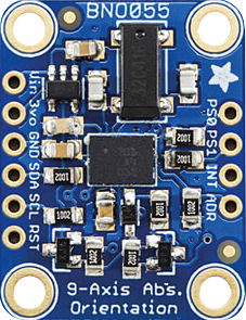
 Design with BNO055 in Cirkit Designer
Introduction
The BNO055 is a 9-axis absolute orientation sensor developed by Bosch and distributed by Adafruit. It integrates a 3-axis accelerometer, a 3-axis gyroscope, and a 3-axis magnetometer, along with an onboard microcontroller that fuses the sensor data to provide accurate orientation information. Unlike traditional sensors, the BNO055 eliminates the need for complex sensor fusion algorithms, making it an ideal choice for applications requiring precise motion tracking and orientation.
Explore Projects Built with BNO055
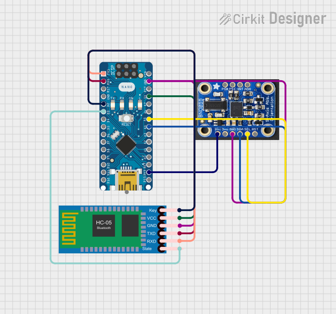 Open Project in Cirkit Designer
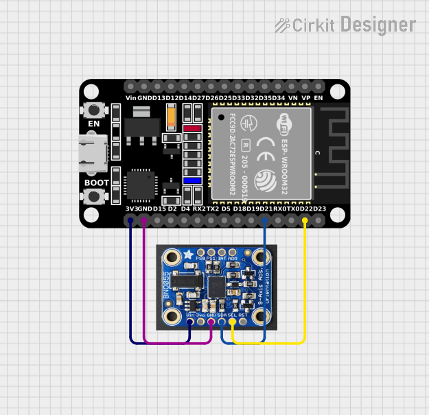 Open Project in Cirkit Designer
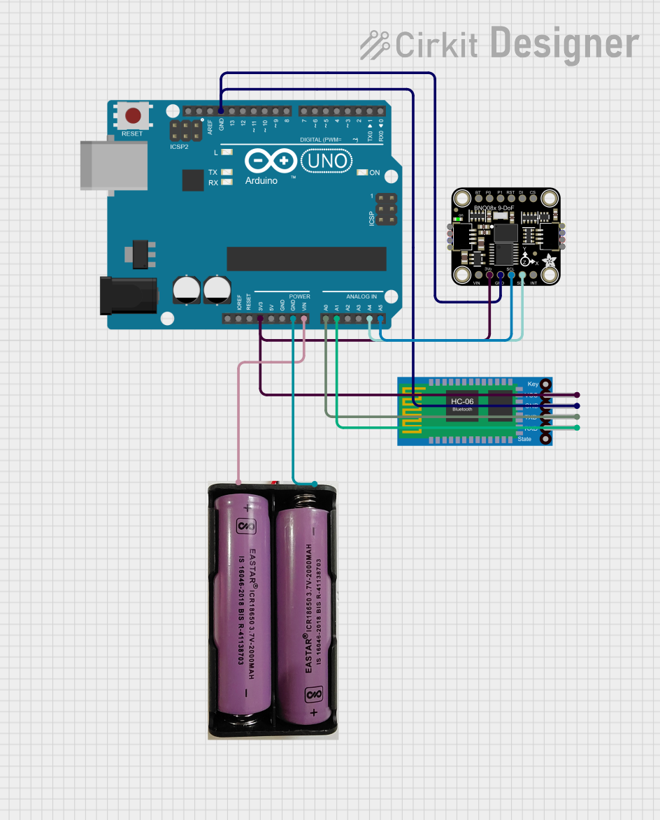 Open Project in Cirkit Designer
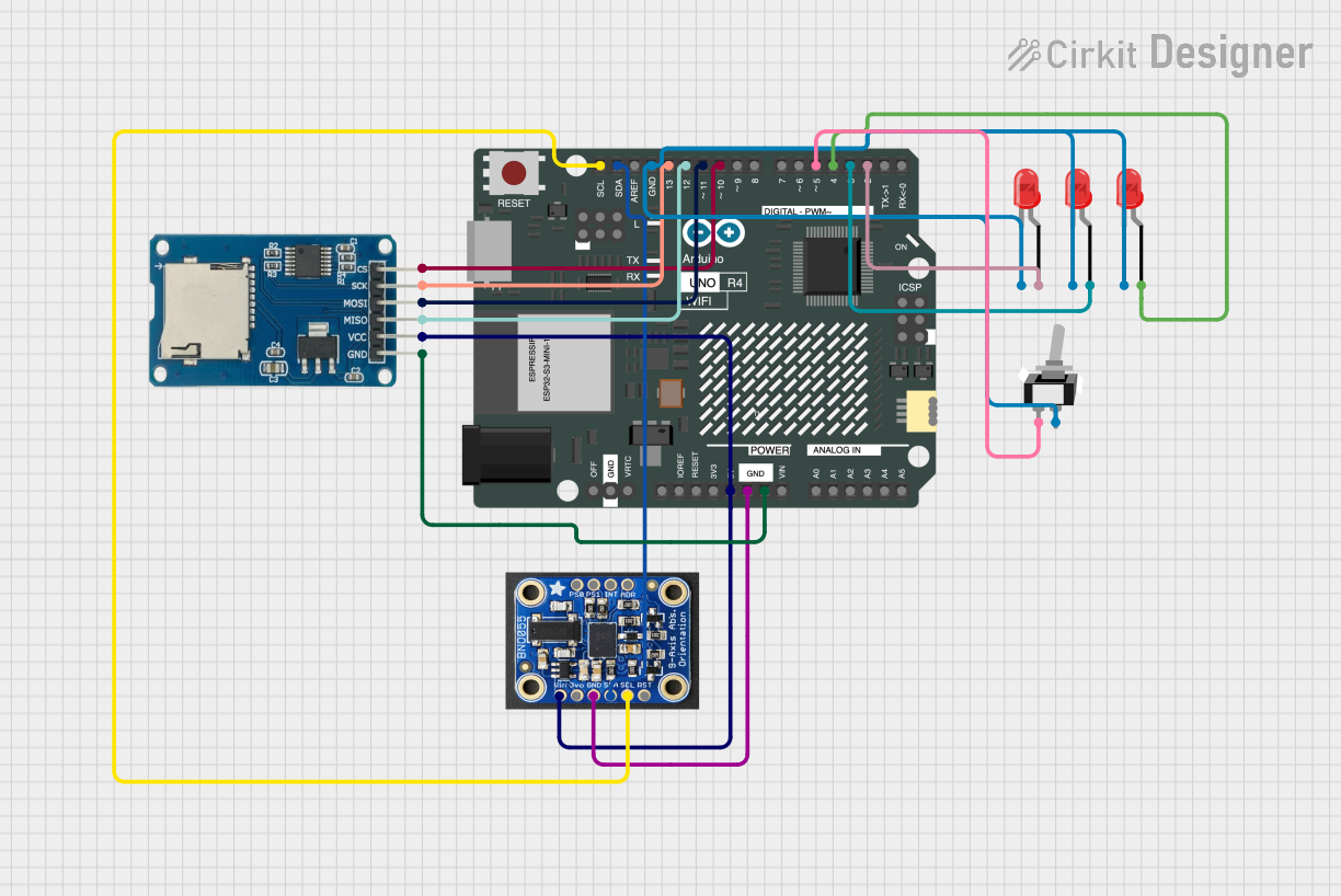 Open Project in Cirkit Designer
Explore Projects Built with BNO055
Open Project in Cirkit DesignerOpen Project in Cirkit DesignerOpen Project in Cirkit DesignerOpen Project in Cirkit DesignerCommon Applications
- Robotics for navigation and control
- Drones for stabilization and orientation
- Virtual reality (VR) and augmented reality (AR) systems
- Wearable devices for motion tracking
- Industrial automation and control systems
Technical Specifications
The BNO055 is a highly versatile sensor with the following key specifications:
| Parameter | Value |
|---|---|
| Operating Voltage | 3.3V to 5V |
| Communication Interfaces | I²C, UART |
| Operating Current | ~12 mA |
| Measurement Range | Accelerometer: ±2g to ±16g |
| Gyroscope: ±125°/s to ±2000°/s | |
| Magnetometer: ±1300 µT | |
| Output Data Rate | Up to 100 Hz |
| Operating Temperature Range | -40°C to +85°C |
| Dimensions | 20.2mm x 18.2mm x 3.8mm |
Pin Configuration
The BNO055 breakout board from Adafruit has the following pin layout:
| Pin | Name | Description |
|---|---|---|
| 1 | VIN | Power input (3.3V to 5V) |
| 2 | GND | Ground connection |
| 3 | SDA | I²C data line (or UART TX in UART mode) |
| 4 | SCL | I²C clock line (or UART RX in UART mode) |
| 5 | PS0 | Protocol selection pin 0 (used to configure I²C or UART mode) |
| 6 | PS1 | Protocol selection pin 1 (used to configure I²C or UART mode) |
| 7 | RST | Reset pin (active low) |
| 8 | INT | Interrupt pin (optional, used for advanced configurations) |
Usage Instructions
Connecting the BNO055 to an Arduino UNO
The BNO055 can be easily interfaced with an Arduino UNO using the I²C protocol. Follow these steps to connect the sensor:
Wiring:
- Connect the
VINpin of the BNO055 to the5Vpin on the Arduino. - Connect the
GNDpin of the BNO055 to theGNDpin on the Arduino. - Connect the
SDApin of the BNO055 to theA4pin on the Arduino. - Connect the
SCLpin of the BNO055 to theA5pin on the Arduino.
- Connect the
Install the Adafruit BNO055 Library:
- Open the Arduino IDE.
- Go to
Sketch > Include Library > Manage Libraries. - Search for "Adafruit BNO055" and install the library.
Example Code: Use the following example code to read orientation data from the BNO055:
#include <Wire.h>
#include <Adafruit_Sensor.h>
#include <Adafruit_BNO055.h>

// Create an instance of the BNO055 sensor
Adafruit_BNO055 bno = Adafruit_BNO055(55);

void setup() {
  Serial.begin(9600);
  // Initialize the BNO055 sensor
  if (!bno.begin()) {
    Serial.println("Error: BNO055 not detected. Check wiring or I2C address.");
    while (1);
  }
  Serial.println("BNO055 initialized successfully!");
  bno.setExtCrystalUse(true); // Use external crystal for better accuracy
}

void loop() {
  // Get the Euler angles (heading, roll, pitch)
  sensors_event_t event;
  bno.getEvent(&event);

  // Print orientation data to the Serial Monitor
  Serial.print("Heading: ");
  Serial.print(event.orientation.x);
  Serial.print("°, Roll: ");
  Serial.print(event.orientation.y);
  Serial.print("°, Pitch: ");
  Serial.print(event.orientation.z);
  Serial.println("°");

  delay(500); // Delay for readability
}
Important Considerations
- Power Supply: Ensure the sensor is powered within its operating voltage range (3.3V to 5V).
- I²C Pull-Up Resistors: The BNO055 breakout board includes onboard pull-up resistors for the I²C lines. Avoid adding external pull-ups unless necessary.
- External Crystal: For improved accuracy, the BNO055 can use an external crystal oscillator. This is enabled by default on the Adafruit breakout board.
- Mounting Orientation: The sensor's orientation affects its readings. Ensure it is mounted securely and aligned with your system's coordinate axes.
Troubleshooting and FAQs
Common Issues
Sensor Not Detected:
- Cause: Incorrect wiring or I²C address mismatch.
- Solution: Double-check the connections and ensure the I²C address is set to
0x28(default).
Inaccurate Readings:
- Cause: Magnetic interference or improper calibration.
- Solution: Perform a full calibration using the Adafruit library's calibration example.
No Output on Serial Monitor:
- Cause: Incorrect baud rate or missing
Serial.begin()in the code. - Solution: Ensure the baud rate in the code matches the Serial Monitor's setting.
- Cause: Incorrect baud rate or missing
FAQs
Can the BNO055 be used with a 3.3V microcontroller?
- Yes, the BNO055 operates at 3.3V and is compatible with 3.3V logic levels.
How do I switch between I²C and UART modes?
- Use the
PS0andPS1pins to configure the communication protocol:- I²C mode:
PS0 = 0,PS1 = 0(default) - UART mode:
PS0 = 1,PS1 = 0
- I²C mode:
- Use the
What is the maximum cable length for I²C communication?
- The maximum length depends on the pull-up resistor values and the I²C clock speed. For reliable communication, keep the cable length under 1 meter.
By following this documentation, you can effectively integrate the BNO055 into your projects and leverage its powerful orientation sensing capabilities.