
How to Use BASIC Stamp 2px24: Examples, Pinouts, and Specs
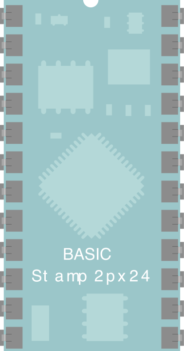
 Design with BASIC Stamp 2px24 in Cirkit Designer
Introduction
The BASIC Stamp 2px24 (BS2PX-IC), manufactured by Parallax Inc., is a powerful microcontroller module that integrates a BASIC interpreter with a microprocessor. This combination allows users to easily program and control electronic devices without requiring extensive knowledge of low-level programming languages. The module is compact, versatile, and well-suited for a wide range of applications, including robotics, automation, data acquisition, and educational projects.
Explore Projects Built with BASIC Stamp 2px24
 Open Project in Cirkit Designer
 Open Project in Cirkit Designer
 Open Project in Cirkit Designer
 Open Project in Cirkit Designer
Explore Projects Built with BASIC Stamp 2px24
Open Project in Cirkit DesignerOpen Project in Cirkit DesignerOpen Project in Cirkit DesignerOpen Project in Cirkit DesignerCommon Applications
- Robotics control systems
- Home automation projects
- Data logging and sensor interfacing
- Educational tools for learning microcontroller programming
- Prototyping and small-scale industrial automation
Technical Specifications
The BASIC Stamp 2px24 is designed to provide high performance and ease of use. Below are its key technical details:
Key Specifications
| Parameter | Value |
|---|---|
| Manufacturer | Parallax Inc. |
| Part Number | BS2PX-IC |
| Operating Voltage | 5 V DC |
| Operating Current | 50 mA (typical) |
| Clock Speed | 20 MHz |
| Program Execution Speed | ~19,000 instructions per second |
| Program Memory | 16 KB (EEPROM) |
| RAM | 128 bytes |
| I/O Pins | 16 (TTL-compatible) |
| Communication Protocols | Serial (TTL-level, 9600-115200 bps) |
| Dimensions | 1.2" x 0.6" (30.5 mm x 15.2 mm) |
| Operating Temperature | -40°C to +85°C |
Pin Configuration
The BASIC Stamp 2px24 features a 24-pin DIP (Dual Inline Package) layout. Below is the pin configuration and description:
| Pin Number | Pin Name | Description |
|---|---|---|
| 1 | VSS | Ground (0 V) |
| 2 | VDD | Power supply input (5 V DC) |
| 3-18 | P0-P15 | General-purpose I/O pins (TTL-compatible) |
| 19 | RES | Reset pin (active low) |
| 20 | ATN | Attention pin for programming/debugging |
| 21-24 | NC | Not connected |
Usage Instructions
The BASIC Stamp 2px24 is designed for ease of use, making it an excellent choice for both beginners and experienced users. Below are the steps and best practices for using the module in a circuit.
Connecting the BASIC Stamp 2px24
- Power Supply: Connect the VDD pin to a regulated 5 V DC power source and the VSS pin to ground.
- I/O Pins: Use the P0-P15 pins for interfacing with sensors, actuators, or other peripherals. These pins can be configured as input or output in the program.
- Programming: Use the ATN pin and a serial connection to upload programs to the module. Parallax provides a dedicated programming environment called the BASIC Stamp Editor.
- Reset: The RES pin can be used to manually reset the module if needed.
Programming the BASIC Stamp 2px24
The module is programmed using PBASIC, a simple and intuitive programming language. Below is an example of a basic program to blink an LED connected to pin P0:
' Program: Blink_LED.bs2
' Description: This program blinks an LED connected to pin P0 at 1-second intervals.

DO
  HIGH 0          ' Set pin P0 to HIGH (turn on LED)
  PAUSE 1000      ' Wait for 1 second
  LOW 0           ' Set pin P0 to LOW (turn off LED)
  PAUSE 1000      ' Wait for 1 second
LOOP
Best Practices
- Use a regulated 5 V power supply to ensure stable operation.
- Avoid exceeding the current limits of the I/O pins (20 mA per pin, 50 mA total).
- Use pull-up or pull-down resistors for input pins to prevent floating states.
- Always verify connections before powering the module to avoid damage.
Using with Arduino UNO
The BASIC Stamp 2px24 can communicate with an Arduino UNO via serial communication. Below is an example Arduino sketch to send data to the BASIC Stamp:
// Arduino Sketch: Send_Data_To_BS2PX.ino
// Description: Sends a message to the BASIC Stamp 2px24 via serial communication.

void setup() {
  Serial.begin(9600); // Initialize serial communication at 9600 bps
}

void loop() {
  Serial.println("Hello, BASIC Stamp!"); // Send message to BASIC Stamp
  delay(1000); // Wait for 1 second before sending the next message
}
Troubleshooting and FAQs
Common Issues and Solutions
Module Not Responding
- Cause: Incorrect power supply or loose connections.
- Solution: Verify that the VDD and VSS pins are properly connected to a 5 V DC power source and ground.
Program Upload Fails
- Cause: Incorrect serial connection or ATN pin not connected.
- Solution: Ensure the ATN pin is connected and the serial cable is properly connected to the programming interface.
I/O Pins Not Working
- Cause: Pins configured incorrectly in the program.
- Solution: Double-check the PBASIC code to ensure pins are set as input or output as required.
Overheating
- Cause: Excessive current draw or incorrect voltage.
- Solution: Ensure the power supply is regulated at 5 V and the total current draw does not exceed 50 mA.
FAQs
Q: Can the BASIC Stamp 2px24 be powered by batteries?
A: Yes, it can be powered by a 5 V battery pack or a 9 V battery with a voltage regulator.
Q: What is the maximum cable length for serial communication?
A: The maximum cable length depends on the baud rate, but for 9600 bps, a length of up to 50 feet is generally reliable.
Q: Can I use the BASIC Stamp 2px24 with sensors and modules designed for Arduino?
A: Yes, as long as the sensors/modules operate at 5 V and use compatible communication protocols (e.g., digital I/O, serial).
Q: Is the BASIC Stamp 2px24 suitable for real-time applications?
A: While it is not a real-time system, its execution speed (~19,000 instructions per second) is sufficient for many time-sensitive applications.
This concludes the documentation for the BASIC Stamp 2px24. For additional resources, visit the Parallax Inc. website.