How to Use USB C MALE ADAFRUIT 5 PIN: Examples, Pinouts, and Specs
Introduction
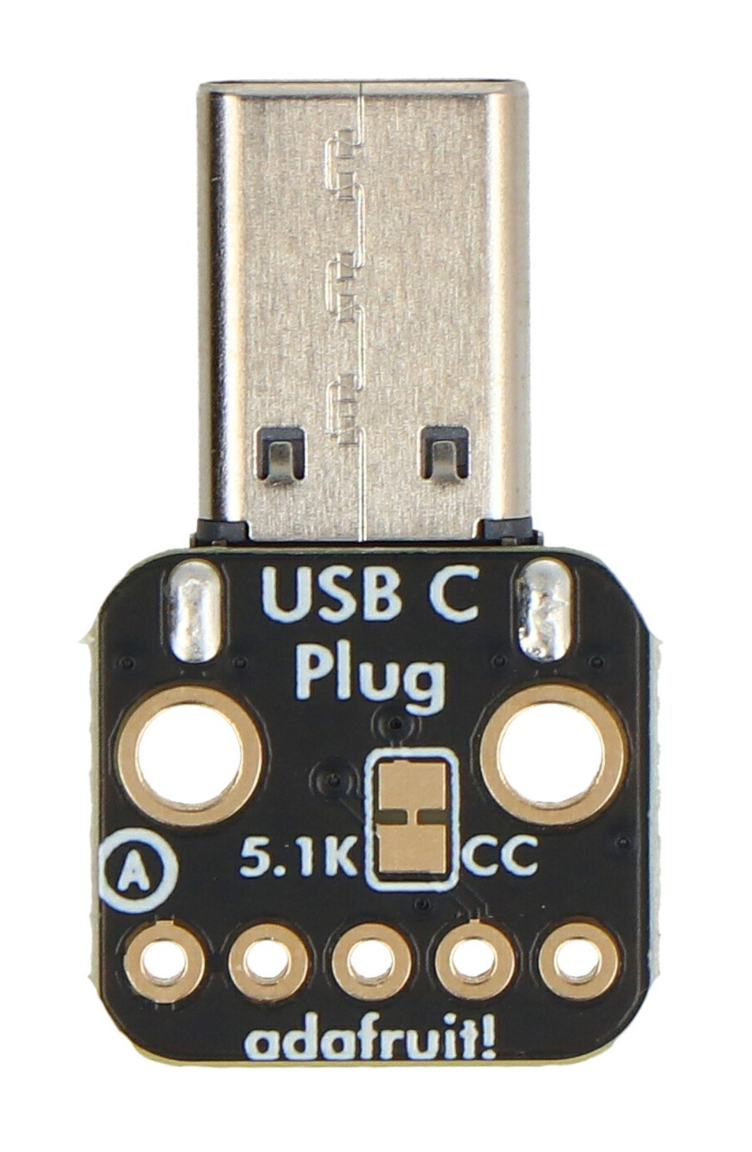
The USB C MALE ADAFRUIT 5 PIN (Manufacturer Part ID: UCMA5P) is a USB Type-C male connector featuring 5 pins. It is designed for modern electronic devices requiring data transfer and power delivery. This component is compact, reliable, and compatible with a wide range of USB-C ports, making it ideal for prototyping and custom hardware designs.
Explore Projects Built with USB C MALE ADAFRUIT 5 PIN


Explore Projects Built with USB C MALE ADAFRUIT 5 PIN
Common Applications and Use Cases
- Power delivery for small electronic devices
- Data transfer in embedded systems
- USB-C interface for custom PCBs
- Prototyping USB-C connections in IoT devices
- Replacement or repair of USB-C connectors in consumer electronics
Technical Specifications
The following table outlines the key technical details of the USB C MALE ADAFRUIT 5 PIN connector:
| Parameter | Specification |
|---|---|
| Manufacturer | Adafruit |
| Part ID | UCMA5P |
| Connector Type | USB Type-C Male |
| Number of Pins | 5 |
| Voltage Rating | Up to 20V |
| Current Rating | Up to 3A |
| Data Transfer Speed | Supports USB 2.0 (480 Mbps) |
| Operating Temperature | -40°C to +85°C |
| Mounting Style | Solderable |
| Dimensions | 8.4mm x 2.4mm x 6.5mm (approximate) |
Pin Configuration and Descriptions
The USB C MALE ADAFRUIT 5 PIN connector has the following pinout:
| Pin Number | Pin Name | Description |
|---|---|---|
| 1 | VBUS | Power supply input (up to 20V, 3A) |
| 2 | D- | USB 2.0 differential data line (negative) |
| 3 | D+ | USB 2.0 differential data line (positive) |
| 4 | CC | Configuration channel for USB-C communication |
| 5 | GND | Ground connection |
Usage Instructions
How to Use the Component in a Circuit
Soldering the Connector:
- Align the USB C MALE ADAFRUIT 5 PIN connector with the PCB pads.
- Use a fine-tipped soldering iron and solder each pin carefully to avoid shorts.
- Ensure proper alignment to maintain reliable connections.
Connecting Power and Data Lines:
- Connect the VBUS pin to the power source (ensure it does not exceed 20V).
- Connect the D- and D+ pins to the corresponding data lines of your microcontroller or USB interface.
- Use the CC pin for USB-C configuration, such as detecting cable orientation or negotiating power delivery.
- Connect the GND pin to the ground plane of your circuit.
Testing the Connection:
- Verify all connections with a multimeter to ensure there are no shorts.
- Plug the connector into a USB-C port and test power delivery or data transfer functionality.
Important Considerations and Best Practices
- Voltage and Current Limits: Do not exceed the rated voltage (20V) or current (3A) to avoid damaging the connector or connected devices.
- Cable Orientation: USB-C is reversible, so ensure your circuit handles both orientations correctly using the CC pin.
- Heat Management: Avoid prolonged exposure to high temperatures during soldering to prevent damage to the connector.
- Data Line Protection: Use ESD protection diodes on the D- and D+ lines to safeguard against electrostatic discharge.
Example: Using with Arduino UNO
Although the Arduino UNO does not natively support USB-C, you can use this connector to power the board or interface with USB peripherals. Below is an example of powering an Arduino UNO using the USB C MALE ADAFRUIT 5 PIN connector:
// Example: Powering Arduino UNO via USB-C
// Ensure the VBUS pin is connected to the Arduino's VIN pin
// and the GND pin is connected to the Arduino's GND pin.

// No additional code is required for basic power delivery.
// Ensure the input voltage on VBUS is between 7V and 12V
// for proper operation of the Arduino UNO's voltage regulator.
Troubleshooting and FAQs
Common Issues Users Might Face
No Power Delivery:
- Cause: Incorrect connection of the VBUS or GND pins.
- Solution: Double-check the soldering and ensure proper polarity.
Data Transfer Not Working:
- Cause: Misaligned or unsoldered D- and D+ pins.
- Solution: Inspect the solder joints and verify continuity with a multimeter.
Overheating During Soldering:
- Cause: Excessive heat applied to the connector.
- Solution: Use a temperature-controlled soldering iron and limit soldering time to a few seconds per pin.
USB-C Orientation Issues:
- Cause: Improper handling of the CC pin.
- Solution: Implement circuitry to detect cable orientation if required for your application.
Solutions and Tips for Troubleshooting
- Use a USB-C breakout board for easier prototyping if soldering directly to the connector is challenging.
- Verify the power source voltage and current ratings before connecting to the VBUS pin.
- If data transfer issues persist, check for noise or interference on the D- and D+ lines and consider adding filtering capacitors.
- Refer to the USB-C specification for advanced features like power delivery negotiation or alternate modes.
By following these guidelines, you can effectively integrate the USB C MALE ADAFRUIT 5 PIN connector into your projects.