How to Use 3,5mm Klinkenstecker 4-polig Adapter Terminal: Examples, Pinouts, and Specs
Introduction
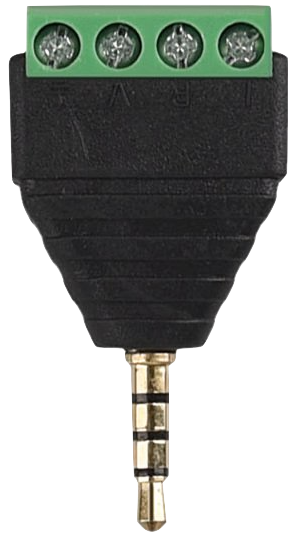
The 3.5mm Klinkenstecker 4-polig Adapter Terminal is a versatile 4-pole audio jack adapter designed for connecting audio devices. It supports stereo sound output and microphone input within a single connector, making it ideal for modern audio applications. This component is commonly used in audio systems, headphones with microphones, smartphones, and other multimedia devices. Its terminal block design allows for easy wiring without the need for soldering, making it a convenient choice for prototyping and DIY projects.
Explore Projects Built with 3,5mm Klinkenstecker 4-polig Adapter Terminal


Explore Projects Built with 3,5mm Klinkenstecker 4-polig Adapter Terminal
Common Applications:
- Connecting headphones with integrated microphones to audio devices
- Audio signal routing in multimedia systems
- DIY audio projects and prototyping
- Interfacing with smartphones, tablets, and laptops
- Repair or replacement of damaged 3.5mm audio connectors
Technical Specifications
Key Technical Details:
- Connector Type: 3.5mm TRRS (Tip-Ring-Ring-Sleeve) audio jack
- Poles: 4 (Stereo Left, Stereo Right, Microphone, Ground)
- Terminal Type: Screw terminal block for easy wiring
- Material: Durable plastic housing with metal contacts
- Dimensions: Approximately 35mm x 15mm x 12mm
- Compatibility: Supports CTIA (Cellular Telecommunications Industry Association) standard pinout
Pin Configuration and Descriptions:
The 3.5mm TRRS connector has four distinct poles, which are mapped to the terminal block for easy wiring. Below is the pin configuration:
| Pin Name | TRRS Position | Function | Terminal Block Label |
|---|---|---|---|
| Tip | 1st position | Left audio channel (L) | L |
| Ring 1 | 2nd position | Right audio channel (R) | R |
| Ring 2 | 3rd position | Microphone input (Mic) | MIC |
| Sleeve | 4th position | Ground (GND) | GND |
Usage Instructions
How to Use the Component in a Circuit:
- Identify the Pinout: Refer to the pin configuration table above to understand the function of each terminal.
- Connect Wires to the Terminal Block:
- Loosen the screws on the terminal block.
- Insert the appropriate wires into the labeled terminals (L, R, MIC, GND).
- Tighten the screws to secure the wires.
- Integrate into Your Circuit:
- Connect the other ends of the wires to your audio device or circuit.
- Ensure proper alignment of the TRRS jack with the corresponding device port.
- Test the Connection:
- Plug the 3.5mm jack into the audio device.
- Verify stereo sound output and microphone input functionality.
Important Considerations and Best Practices:
- CTIA vs. OMTP Standards: Ensure your device follows the CTIA standard, as this adapter is designed for CTIA pinout. OMTP devices may require a different configuration.
- Avoid Short Circuits: Double-check wiring to prevent short circuits between terminals.
- Cable Strain Relief: Use strain relief mechanisms to avoid stress on the wires connected to the terminal block.
- Signal Quality: Use shielded cables for better audio signal quality and reduced interference.
Example: Connecting to an Arduino UNO
The 3.5mm Klinkenstecker 4-polig Adapter Terminal can be used to interface audio signals with an Arduino UNO. Below is an example of reading microphone input using the Arduino's analog pin:
// Example: Reading microphone input from the 3.5mm adapter terminal
// Connect the MIC terminal to Arduino A0, and GND to Arduino GND.

const int micPin = A0;  // Microphone input connected to analog pin A0

void setup() {
  Serial.begin(9600);  // Initialize serial communication
}

void loop() {
  int micValue = analogRead(micPin);  // Read the microphone signal
  Serial.println(micValue);          // Print the signal value to the Serial Monitor
  delay(100);                        // Delay for readability
}
Note: This example assumes the microphone signal is analog and compatible with the Arduino's input voltage range (0-5V). Use a preamplifier if the microphone signal is too weak.
Troubleshooting and FAQs
Common Issues and Solutions:
No Sound or Microphone Input:
- Cause: Incorrect wiring or loose connections.
- Solution: Double-check the wiring and ensure all screws are tightened securely.
Static or Noise in Audio:
- Cause: Poor cable shielding or interference.
- Solution: Use shielded cables and keep the adapter away from sources of electromagnetic interference.
Incompatible Pinout:
- Cause: Device uses OMTP standard instead of CTIA.
- Solution: Use a CTIA-to-OMTP adapter or reconfigure the wiring.
Adapter Not Fitting Properly:
- Cause: Dust or debris in the 3.5mm jack.
- Solution: Clean the jack and ensure proper alignment when inserting.
FAQs:
Q: Can this adapter be used with a mono audio device?
A: Yes, but only the left audio channel (L) will be active. For mono output, connect the L and R terminals together.Q: Is soldering required to use this adapter?
A: No, the screw terminal block eliminates the need for soldering.Q: Can I use this adapter for video signals?
A: No, this adapter is designed specifically for audio signals and microphone input.Q: How do I identify the CTIA pinout on my device?
A: Most modern smartphones and laptops use the CTIA standard. Refer to your device's documentation for confirmation.
By following this documentation, you can effectively use the 3.5mm Klinkenstecker 4-polig Adapter Terminal in your audio projects with ease and confidence.