How to Use Adjustable Boost Module: Examples, Pinouts, and Specs
Introduction
The Adjustable Boost Module is a versatile power supply circuit designed to increase input voltage to a higher, adjustable output voltage. This component is widely used in applications where a stable, higher voltage is required from a lower voltage source, such as batteries or low-voltage power supplies. Its compact design and adjustable output make it ideal for powering devices like LED strips, microcontrollers, and portable electronics.
Explore Projects Built with Adjustable Boost Module


Explore Projects Built with Adjustable Boost Module
Common Applications and Use Cases
- Powering high-voltage devices from low-voltage batteries
- Driving LED strips or lighting systems
- Supplying voltage to microcontrollers and sensors
- Portable power banks and USB chargers
- DIY electronics projects requiring variable voltage
Technical Specifications
The Adjustable Boost Module is designed to provide reliable and efficient voltage conversion. Below are its key technical details:
| Parameter | Specification |
|---|---|
| Input Voltage Range | 3V to 32V |
| Output Voltage Range | 5V to 35V (adjustable) |
| Maximum Output Current | 2A (continuous), 3A (peak) |
| Efficiency | Up to 92% |
| Switching Frequency | 150 kHz |
| Dimensions | Typically 43mm x 21mm x 14mm |
| Adjustment Method | Multi-turn potentiometer |
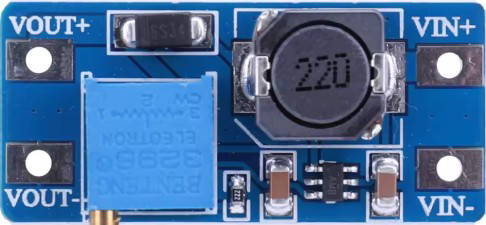
Pin Configuration and Descriptions
The Adjustable Boost Module typically has four pins or terminals for input and output connections:
| Pin/Terminal | Label | Description |
|---|---|---|
| IN+ | Input + | Positive input voltage terminal |
| IN- | Input - | Negative input voltage terminal (ground) |
| OUT+ | Output + | Positive output voltage terminal |
| OUT- | Output - | Negative output voltage terminal (ground) |
Usage Instructions
How to Use the Adjustable Boost Module in a Circuit
Connect the Input Voltage:
- Connect the positive terminal of your power source to the
IN+pin. - Connect the negative terminal of your power source to the
IN-pin. - Ensure the input voltage is within the specified range (3V to 32V).
- Connect the positive terminal of your power source to the
Connect the Output Load:
- Connect the positive terminal of your load to the
OUT+pin. - Connect the negative terminal of your load to the
OUT-pin.
- Connect the positive terminal of your load to the
Adjust the Output Voltage:
- Use a small screwdriver to turn the multi-turn potentiometer on the module.
- Turn clockwise to increase the output voltage or counterclockwise to decrease it.
- Use a multimeter to measure the output voltage while adjusting.
Power On:
- Once all connections are secure, power on the input source.
- Verify the output voltage and ensure it matches your requirements.
Important Considerations and Best Practices
- Input Voltage: Ensure the input voltage is within the specified range to avoid damaging the module.
- Output Current: Do not exceed the maximum output current (2A continuous, 3A peak) to prevent overheating.
- Heat Dissipation: For high-power applications, consider adding a heatsink or active cooling to the module.
- Polarity: Double-check the polarity of your connections to avoid short circuits or damage.
- Load Testing: Test the module with a dummy load before connecting sensitive devices.
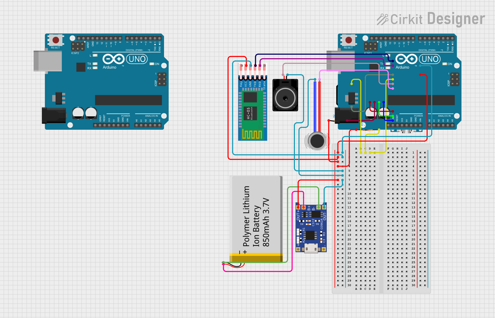
Example: Using the Adjustable Boost Module with an Arduino UNO
The Adjustable Boost Module can be used to power an Arduino UNO from a low-voltage source, such as a 3.7V Li-ion battery. Below is an example setup:
- Connect the battery's positive terminal to
IN+and negative terminal toIN-. - Adjust the output voltage to 9V using the potentiometer.
- Connect
OUT+to the Arduino's VIN pin andOUT-to the GND pin.
Here is a simple Arduino code example to blink an LED, powered by the Adjustable Boost Module:
// Simple LED Blink Example
// Ensure the Adjustable Boost Module is set to output 9V for the Arduino UNO.

const int ledPin = 13; // Built-in LED pin on Arduino UNO

void setup() {
  pinMode(ledPin, OUTPUT); // Set the LED pin as an output
}

void loop() {
  digitalWrite(ledPin, HIGH); // Turn the LED on
  delay(1000);                // Wait for 1 second
  digitalWrite(ledPin, LOW);  // Turn the LED off
  delay(1000);                // Wait for 1 second
}
Troubleshooting and FAQs
Common Issues and Solutions
No Output Voltage:
- Cause: Incorrect input connections or insufficient input voltage.
- Solution: Verify the input connections and ensure the input voltage is within the specified range.
Output Voltage Not Adjustable:
- Cause: Faulty potentiometer or incorrect adjustment.
- Solution: Check the potentiometer for damage and adjust it carefully while monitoring the output voltage.
Overheating:
- Cause: Excessive load current or poor heat dissipation.
- Solution: Reduce the load current or add a heatsink to the module.
Module Not Powering On:
- Cause: Reverse polarity or damaged components.
- Solution: Double-check the polarity of the input connections and inspect the module for visible damage.
FAQs
Q: Can I use the Adjustable Boost Module to power a 12V LED strip from a 5V USB power source?
A: Yes, as long as the input current from the USB source is sufficient to meet the power requirements of the LED strip. Ensure the output voltage is set to 12V.
Q: What happens if I exceed the maximum output current?
A: Exceeding the maximum output current can cause the module to overheat or shut down. Prolonged overcurrent conditions may damage the module.
Q: Can I use this module with a solar panel?
A: Yes, the module can be used with a solar panel, provided the panel's output voltage and current are within the module's input range.
Q: Is the output voltage stable under varying loads?
A: The module is designed to provide stable output voltage under normal operating conditions. However, significant load variations may cause minor fluctuations.
By following this documentation, you can effectively use the Adjustable Boost Module in your projects and troubleshoot common issues.