How to Use bms 10: Examples, Pinouts, and Specs
Introduction
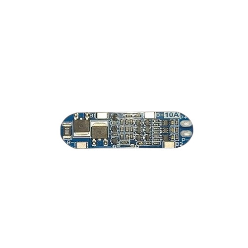
The BMS 10 by dgwydgg (Manufacturer Part ID: dwudgt) is a robust Battery Management System (BMS) designed to manage and monitor the performance of battery packs. It ensures safe operation by balancing cell voltages, protecting against overcharging, deep discharging, and thermal events. This component is ideal for applications requiring reliable battery management, such as electric vehicles, renewable energy systems, and portable electronics.
Explore Projects Built with bms 10


Explore Projects Built with bms 10
Common Applications
- Electric vehicles (EVs) and hybrid vehicles
- Solar energy storage systems
- Uninterruptible power supplies (UPS)
- Portable electronics and power tools
- Industrial battery systems
Technical Specifications
Key Technical Details
| Parameter | Value |
|---|---|
| Input Voltage Range | 12V to 48V |
| Maximum Current Handling | 100A |
| Cell Configuration | 3S to 16S (3 to 16 cells in series) |
| Balancing Current | 50mA to 200mA per cell |
| Overcharge Protection | 4.2V ± 0.05V per cell |
| Overdischarge Protection | 2.5V ± 0.05V per cell |
| Operating Temperature Range | -20°C to 60°C |
| Communication Interface | UART, I2C |
| Dimensions | 100mm x 60mm x 10mm |
Pin Configuration and Descriptions
| Pin Number | Pin Name | Description |
|---|---|---|
| 1 | B+ | Positive terminal of the battery pack |
| 2 | B- | Negative terminal of the battery pack |
| 3 | P+ | Positive terminal for load/charger connection |
| 4 | P- | Negative terminal for load/charger connection |
| 5 | C1, C2, ... Cn | Cell voltage sense pins for individual battery cells (C1 for Cell 1, etc.) |
| 6 | UART_TX | UART transmit pin for communication |
| 7 | UART_RX | UART receive pin for communication |
| 8 | I2C_SCL | I2C clock line for communication |
| 9 | I2C_SDA | I2C data line for communication |
| 10 | TEMP | Temperature sensor input |
Usage Instructions
How to Use the BMS 10 in a Circuit
Connect the Battery Pack:
- Connect the positive terminal of the battery pack to the B+ pin.
- Connect the negative terminal of the battery pack to the B- pin.
- Ensure that the cell voltage sense pins (C1, C2, ... Cn) are connected to the corresponding battery cells in series.
Connect the Load and Charger:
- Attach the load's positive terminal to the P+ pin and the negative terminal to the P- pin.
- Similarly, connect the charger to the P+ and P- pins.
Communication Interface:
- Use the UART or I2C pins to interface with a microcontroller or monitoring system for real-time data and control.
Temperature Monitoring:
- Connect a compatible temperature sensor to the TEMP pin to monitor the battery pack's temperature.
Important Considerations and Best Practices
- Cell Matching: Ensure all cells in the battery pack are of the same type, capacity, and state of charge (SOC) to avoid imbalances.
- Wiring: Use appropriately rated wires for the current and voltage levels to prevent overheating or voltage drops.
- Cooling: If operating near the upper temperature limit, consider adding a cooling mechanism to maintain safe operation.
- Firmware Updates: Check for firmware updates from the manufacturer to ensure optimal performance and compatibility.
Example: Connecting BMS 10 to an Arduino UNO
The following example demonstrates how to read battery voltage data from the BMS 10 using the UART interface.
#include <SoftwareSerial.h>

// Define RX and TX pins for UART communication
SoftwareSerial BMS(10, 11); // RX = Pin 10, TX = Pin 11

void setup() {
  Serial.begin(9600);       // Initialize Serial Monitor
  BMS.begin(9600);          // Initialize UART communication with BMS
  Serial.println("BMS 10 Communication Initialized");
}

void loop() {
  if (BMS.available()) {
    // Read data from BMS and print to Serial Monitor
    String data = BMS.readString();
    Serial.println("BMS Data: " + data);
  }
  delay(1000); // Wait for 1 second before next read
}
Notes:
- Ensure the BMS 10 is powered and properly connected to the Arduino UNO.
- Use a level shifter if the BMS operates at a voltage level different from the Arduino's logic level (5V).
Troubleshooting and FAQs
Common Issues and Solutions
| Issue | Possible Cause | Solution |
|---|---|---|
| BMS not powering on | Incorrect wiring or loose connections | Verify all connections and ensure proper polarity. |
| Cells not balancing | Cell voltages too far apart | Pre-balance cells before connecting to the BMS. |
| Overcharge/Overdischarge protection | Faulty cell or incorrect configuration | Check cell health and ensure proper configuration of the BMS. |
| Communication not working | Incorrect UART/I2C settings | Verify baud rate, wiring, and communication protocol settings. |
| High temperature warning | Poor ventilation or excessive current | Improve cooling or reduce load/charging current. |
FAQs
Can the BMS 10 handle lithium-ion and LiFePO4 batteries?
- Yes, the BMS 10 is compatible with both lithium-ion and LiFePO4 chemistries. Ensure the voltage thresholds are configured accordingly.
What happens if a cell is damaged?
- The BMS will detect the fault and may disconnect the battery pack to prevent further damage. Replace the damaged cell before reuse.
Can I use the BMS 10 for parallel battery packs?
- The BMS 10 is designed for series configurations. For parallel packs, ensure each series string has its own BMS.
How do I update the firmware?
- Refer to the manufacturer's documentation for firmware update procedures via the UART or I2C interface.
By following this documentation, users can effectively integrate and operate the BMS 10 in their battery-powered systems.